
Search the Knowledge Base
High Torque GRBL Bundle – V2


2.0 Limit Switch Wiring
The limit switch kits are used as hard limits for your machine. The limit switch kit includes a set of spade connectors which will be used to connect onto the terminals of the limit switch.
Crimp the included red spade connectors onto the appropriate limit switch cable. Connect the Blue wire to Normally Closed (NC) and the White wire (illustrated as black in this guide) to Common (C).
We use the Normally Closed Configuration as it is more resistant to Electromagnetic Inteference or EMI and if the wire is damaged, it is detected by the controller.
Please see the table below for the pinout.
| Axis | Arduino Pin | Limit Switch Pin |
| X-Axis Limit Switch | 9 | NC |
| Y-Axis Limit Switch | 10 | NC |
| Z-Axis Limit Switch | 11 | NC |

3.0 Emergency Stop Switch Wiring
The emergency stop switch cuts off power to the power supply and therefore the stepper motor drivers. This is a must have safety feature should you require to stop your machine in as little time as possible during an emergency.
Wiring this switch requires some disassembly. Open the switch housing by unscrewing the 4 screws with a Phillips head screwdriver to access the terminals
Because this emergency stop is being wired on the mains voltage section of your power supply, a licenced electrician or similarly qualified individual is required to wire this step.
The power supply is shipped with a power supply cover to protect the users from high voltage. Please read the guide on installing it here.


4.5 Closed Loop Stepper Motor
A Closed Loop Stepper Motor has an encoder cable. This is a 2 loom cable. One loom has 4 wires for the motor coil, the other loom has 6 wires for the motor encoder. We have two kinds of closed loop Stepper motor drivers; the HSS57 and HBS57. The wiring of both is identical.
4.6 Closed Loop Stepper Motor Driver Settings
The recommended settings for the closed loop stepper motor are shown below
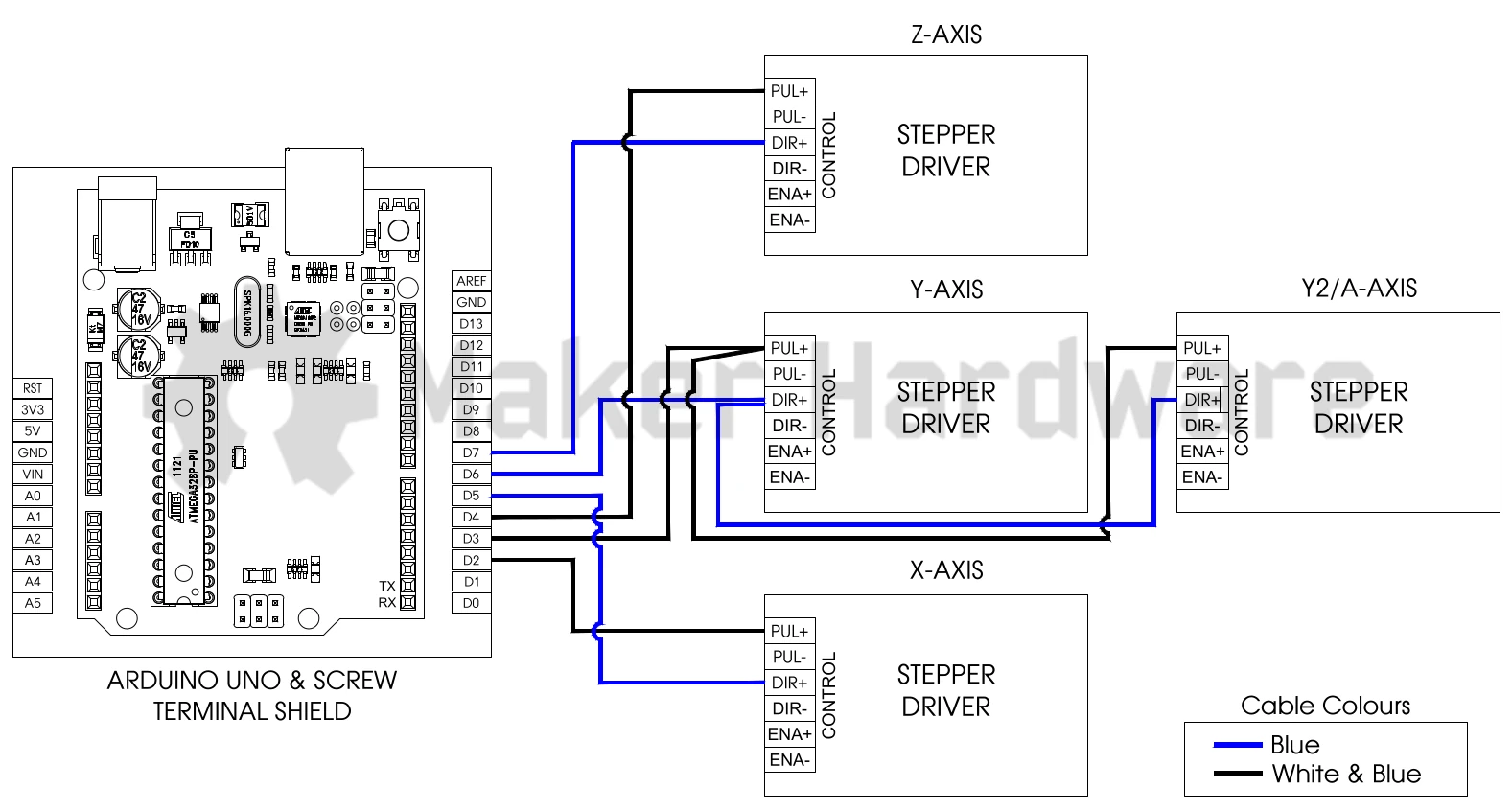
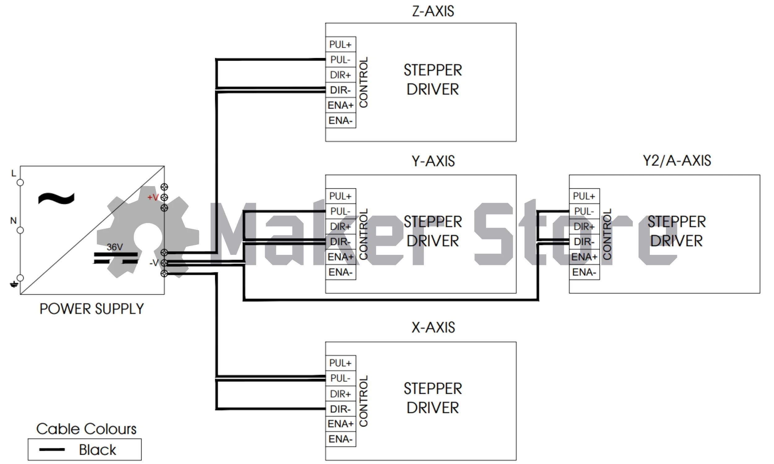
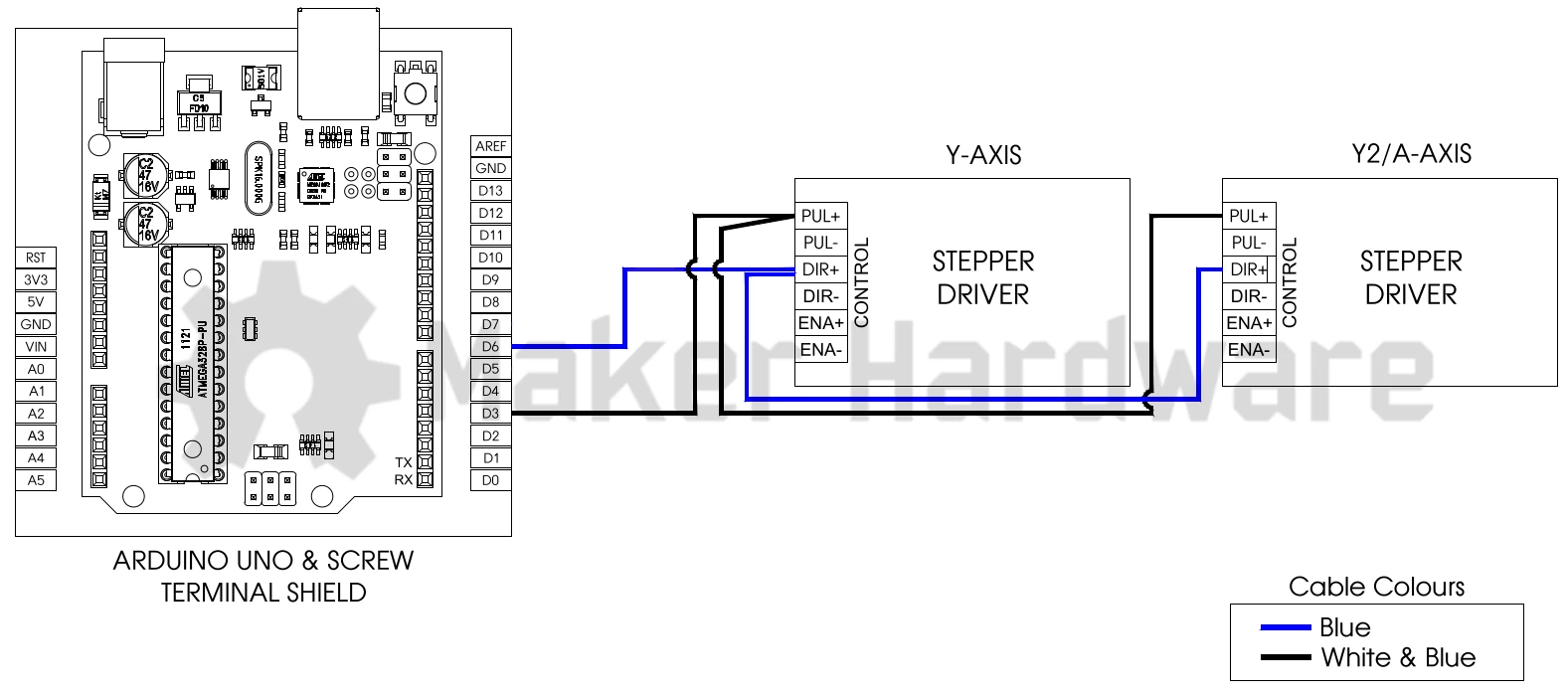
4.7 Closed Loop Stepper Motor Driver Wiring


Your Arduino compatible microcontroller comes with the boot loader pre-flashed and is ready to be flashed with GRBL. Flashing GRBL on the Arduino is pretty straight forward. Adhere to the following steps: Download and install the Arduino IDE
- Download the Arduino IDE here
- Locate the downloaded file. By default it should be in your Downloads folder.
- Double click to run the installation process. Follow the prompts to install.
Download and install the GRBL libraries.
- Download GRBL V1.1 here
- Note where the file has been downloaded and extract the .zip file titled grbl.
- After the extracting, copy the extracted folder to your Arduino Libraries folder. (By Default, your libraries folder should be in: (C:\Program Files (x86)\Arduino\libraries)
Configuring your Arduino
- Before uploading any code, you must configure your board by selecting a board and selecting the port that the board is connected to.
Open the Arduino IDE and you will see a blank sketch such as below:

Open in new tab to zoom. To select the board and port, click on “Select Board” and choose that port that your board is connected to. It will also list the port number. In this case the Arduino Uno is selected and connected to COM 7.

Open in new tab to zoom.


Flashing GRBL
To flash GRBL click on File- Examples – grbl – grblUpload and a grbl sketch will be shown. Upload the sketch to the arduino by clicking on the arrow button highlighted by the yellow square.

Open in new tab to zoom. - Upon a successful upload, the IDE will report “Done Uploading”.

Open in new tab to zoom.


To control a CNC machine, you will need gcode sending software. There are many types of gcode senders out there and we recommend ioSender. ioSender is a powerful gcode sender used for CNC control. Its feature rich and easy to use interface makes it an ideal CNC gcode sender.
Please see the installation steps below:
- You can download ioSender here.
- Locate the downloaded file. By default, it should be in your Downloads folder.
- Unzip the downloaded file and copy the folder to your desktop.
- Open the folder and locate ‘ioSender.exe’. Double click the file to open it. It will initially launch with the following screen. Select the port and click on toggle DTR.

- The following ioSender Screen will show. The main aspects of the program have been highlighted for you.

Open in new tab to zoom. - It is recommended to configure your ioSender’s jog panel settings before you begin. Click on the Settings: App and adjust the the feed rate and jog distances in the UI Jogging highlighted by the green rectangle. You may adjust to your discretion. The recommended list is below. Restart ioSender for the changes to take effect.

Open in new tab to zoom.


Machine Profiles:
ioSender can be used to load these machine profiles. Please see below:
Firstly, download the machine profiles here. Follow the installation guide below:
- Locate the downloaded file in your Downloads folder. Right click the file and unzip the file.
- Opening the file will show a list of folders each for a different machine.
Navigate to the folder containing the brand of the machine series you own. The image below shows the list of machines in our inventory. For example, if you own a WorkBee 1000 x 1000mm kit, navigate to the WorkBee folder.

Open in new tab to zoom. - Locate the configuration file of the machine that you have. Take note of the motors attached to your machines. We offer High Torque and Standard Torque motors.

Open in new tab to zoom. - Copy the profile and naviogate to the ioSender folder and paste it.

Open in new tab to zoom. - In ioSender, navigate to the Settings: Grbl menu. The following menu will show.
Open in new tab to zoom. - Select the Restore button highlighted by the Green Square.

Open in new tab to zoom. - You will be taken to the main directory where you pasted the mchine profile. Select the machine profile to load it.

Open in new tab to zoom. - After it has loaded, you can see the settings list change. The settings will then be saved.
Open in new tab to zoom.


Depending on the motor wiring and machine setup, you may need to invert the direction of an axis if it is going the wrong way. See the correct convention below:

If your machine is moving along the convention set above, no action is required to adjust the motor direction. You may proceed to the Homing Direction section.
To invert an axis, please refer to the table below. For example, if only the X-Axis is inverted, change the setting ID #3 in the Settings: Grbl menu using the table below. As X -Axis only needs to be inverted, change ID #3 to 1 and click the save button indicated by the green square.


Homing Direction
When homing, the machine may attempt to home away from the limit switch. To get the machine homing in the right direction, you can invert the homing direction logic just as the motor direction. For example, if the Z-Axis is homing away from the limit switch, stop the homing cycle by clicking the red Reset button in ioSender.
Using the table below, take note of the axis moving away from the limit switch and invert it accordinly. If for example, the X-Axis is homing in the wrong direction, change ID #23 to 1. If the X-Axis and Y-Axis are both homing in the wrong direction, change ID #23 to 3.

Motor Tuning
To further dial in your machine, we recommend using this tool by Layerfused.com
https://www.layerfused.com/3d-printer-calibration
This tool can be used for CNC application as well. To use it, it is recommended to jog the machine a certain distance and the measure the travelled distance. You can do this by:
- Marking the start position. The X-Axis has been picked for this example. Jog the machine 100mm and mark the finish position. You may use a pencil or texta for this.
- Jog the machine away from the marked section and measure. The machine should have travelled 100mmm. If it did not, take note of the travelled distance as well as the Steps Per mm setting in the Settings: Grbl menu. For the X-Axis it is 100, for the Y-Axis it is 101 and for the Z-Axis it is 102.
- If the X-Axis travelled 99.5mm and the current Steps Per mm is 200, you may enter this information in the calculator.

- The new calculated value is now 201. Insert the 201 value in ID #100.

- Repeat the same process for the other axis.

