
Search the Knowledge Base
E5X MCS T4.1 Controller

1.0 Introduction
The E5X MCS T4.1 (“E5X” for short) is an Ethernet controlled 5 axis Motion Control System powered by a powerfully capable 32-bit Teensy® 4.1. It is an easy to use and powerful motion control system that can drive up to 5 axis (+1 clone/slave) CNC machines.
The E5X is designed to run grblHAL firmware, which is fast becoming the firmware of choice for CNC control due to increased functionality and added features, far surpassing the current 8-bit CNC controllers on the standard port of grbl or grbl esp32.
Teensy® 4.1 was selected as the core controller due to its high processing power and many auxiliary inputs/outputs (which can be used for future expansion). With an ARM Cortex-M7 processor clocked at 600 MHz it is the fastest microcontroller amongst all grbl and grblHAL compatible microcontrollers. This makes it a powerful controller for many years to come.
Connectivity is through a native ethernet or USB port – depending on the user’s CNC requirements.
The E5X MCS allows for custom motor setups such as high-performance closed-loop stepper motors or servo motors.
The engineers at Maker Store got together and made a list of all the features we wanted in a high-performance CNC controller. The result is the E5X MCS T4.1, a CNC Controller that outclasses all GRBL-based controllers and is modularly adaptive. Powered by a Teensy® 4.1, the E5X exceeds the current available technology, with future upgradability built into the design. As advanced CNC components steadily increase in availability, a capable and adaptable controller to take advantage of these advancements is a must-have for all CNC machines. Proudly designed and tested in Australia by the team at Maker Store – a wholly owned Australian company.
The Maker Store E5X MCS T4.1 is the cutting edge of grbl powered motion control systems with upgradability built into the design. This is the future of CNC and motion control.
1.1 The Name
About the name “E5X MCS T4.1”:
- E5X – Ethernet 5 Axis (+1 Slave)
- MCS – Motion Control System
- T4.1 – Powered by a Teensy® 4.1 Microcontroller
The development team at Maker Store calls it the “E5X” for short.
1.2 Specifications and Requirements

| # | Description | # | Description | # | Description |
| 1 | COMMUNICATION | 11 | LIMIT SWITCH INPUTS | 21 | AUXILIARY OUTPUT LEDs |
| 2 | RESET BUTTON | 12 | MOTOR OUTPUTS | 22 | SPINDLE STATUS LED |
| 3 | DIGITAL INPUT | 13 | MOTOR ALARM STATUS | 23 | LIMIT SWITCH STATUS LEDs |
| 4 | SPINDLE DIGITAL | 14 | CASE BOLTS (x4) | 24 | QR CODE ONLINE DOCUMENTS |
| 5 | SPINDLE ANALOG | 15 | MOUNTING HOLES (x4) | 25 | FUSE BLOWN LED |
| 6 | 5V LASER PWM | 16 | MOTOR ALARM INPUTS 5 or 24V | 26 | HOLD/E-STOP LEDs |
| 7 | DIGITAL OUTPUTS – 24V | 17 | TEENSY® 4.1 MICRO SDC SLOT | 27 | POWER LEDs |
| 8 | DIGITAL INPUTS – 5V | 18 | SERIAL COMMUNICATION | 28 | LIMIT SWITCH FUSE LED |
| 9 | POWER INPUTS | 19 | PROBE/DOOR LEDs | 29 | REVERSE POLARITY LEDs |
| 10 | POWER SWITCH | 20 | DUST/MIST/FLOOD LEDs |
Board Specifications
- High-performance 32-bit controller powered by ARM Cortex-M7 processor @ 600 MHz.
- Ethernet or USB connectivity.
- Full 5-Axis control outputs plus an independent clone/slave axis port.
- Selectable clone axis via on board jumpers - can clone either X, Y, Z, A, or B axis.
- Opto-isolated inputs for DOOR/PROBE/HOLD/START/E-STOP input signals.
- Opto-isolated inputs for all limit switches input signals.
- 4 Auxiliary digital inputs with Schmitt trigger buffer.
- Reverse polarity and short circuit protection.
- Independent stepper motor/servo enable signal for each axis.
- Digital Spindle Enable and Direction outputs.
- 0-10V or 4-20mA spindle speed control outputs.
- 5V PWM laser output.
- Dust extraction relay output.
- All round pluggable 3.81mm pitch screw terminal connectors for I/O. No soldering required.
- 6x 24V Digital Outputs – Mist Coolant, Flood Coolant, Dust Collector and 3 auxiliary outputs controlled by additional M-codes.
- External stepper motor driver support for open/closed loop stepper motor.
- External motor driver support for Servo motors.
- 24V Mechanical and Inductive limit switch compatible.
- Built-in replaceable over-current and short circuit protection fuses.
- Motor alarm inputs for closed loop stepper motors and servo motors for all axes including slave axis.
- Status LEDs for limit switches, alarm inputs, spindle function and digital outputs.
- Full range of status indicator LED for clear and easy diagnostics.
- Serial Communication port for pendants and future expansion.
- SD Card enables G-Code files to be stored on the E5X and accessed via ioSender.
- Strong metal case secures electronics.
Software Requirements
ioSender is the recommended G-code sending software for the E5X MCS. While other grbl compatible G-code senders may work, you will not get the full functionality of the grblHal firmware unless you use ioSender.
Computer Requirements
Windows 10/11 computers are required for the E5X MCS controller and the recommended ioSender G-Code sending software. MAC/Linux operating systems are not yet supported by ioSender and not recommended for grblHAL-based controllers.
Connectivity is through a native ethernet or USB port.
Assumed Knowledge
- Basic understanding of electrical wiring.
- Basic understanding of hand tool use.
Tools Required
You may require tools to mount the controller to a surface (recommended). The controller case comes with 4x M4 mounting holes. The recommended method of mounting the E5X MCS is using 4x 8mm M4 Cap Head Bolts, M4 Shims, Slot Washer (as a spacer) and Tee Nuts to our Aluminium Extrusion.
- 3mm Allen Key – for M4 Cap Head Bolts.
- 2mm Flat Head Screwdriver – for wiring to the connectors.
2.0 Mechanical Drawings
The following drawings show the physical dimensions of the E5X MCS and the mounting hole placements.


All dimensions are in mm
Click to expand
The mounting tabs on the E5X MCS plate are made for M4 screws or bolts. Simply insert M4 bolts or screws through the mounting tabs and into your material of choice on the other side. The E5X MCS can be mounted to a piece of extrusion or flat material such as acrylic or MDF. As the E5X MCS does not require active cooling, it can be mounted in a sealed enclosure.
3.0 E5X Power and Power Inputs
Safety Statement
The author of this document is not liable or responsible for any accidents, injuries, equipment damage, property damage, loss of money or loss of time resulting from improper use of electrical or mechanical or software products.
Assembling electrical and mechanical machine components like power supplies, motors, drivers or other electrical and mechanical components involves dealing with high voltage AC (alternating current) or DC (direct current) and other hazardous items which can be extremely dangerous and needs high attention to detail, experience, knowledge of software, electricity, electro-mechanics and mechanics.
BEFORE MAKING ANY CONNECTIONS OR DISCONNECTIONS POWER MUST BE REMOVED FROM THE DEVICE AND THE CONTROLLER. FAILURE TO DO SO WILL VOID ANY AND ALL WARRANTIES.
Before starting please read through all the instructions.
Note: Any Mains power connections must be installed by a Licensed electrician or suitability qualified person.
All Errors and Omissions Excepted - feedback is, of course, welcome!

The power section of the E5X consists of LED indicators that identify the activated power systems as well as identify incorrect wiring.
This section consists of following components:
[27] Power Status
The POWER status LEDs show which power levels are active for potential fault diagnosis.
The E5X has an onboard 3.3V Low-dropout (LDO) regulator that is powered by the 5V power rail. This 3.3V power can be used for future expansion for peripheral devices such as LCD screens and pendants.

| # | Description | Indication |
| 1 | 3.3V Power Active | Based on what power supply is active (3.3V, 5V or 24V) the associated LED indicator will glow Green. |
| 2 | 5V Power Active | |
| 3 | 24V Power Active |
[29] Inverse Polarity Indicators
The INV POLARITY indicators report whether any of the power input wires are reversed, resulting in reverse polarity. By default, the LED indicators for reverse polarity are off.

| # | Description | Indication |
| 5V | 5V Inverse Polarity In-Use Status Indicator | If the wiring for the 5V circuit is reversed, this LED indicator will glow red. |
| 24V | 24V Inverse Polarity In-Use Status Indicator | If the wiring for the 24V circuit is reversed, this LED indicator will glow red. |
[10] Power Switch
The E5X has a heavy duty rocker switch for switching the controller on and off. This rocker switch is a double pole, double throw switch which turns both the 5V and 24V power inputs on or off.

| # | Description | Function |
| POWER OFF/ON | On/Off Rocker Switch | Switches 5V and 24V power On (Green) or Off (Red) to the E5X. |
[25,28] Fuses
Three fuses are used to protect the E5X controller against damage from overcurrent and short circuits. If a fuse has blown for any reason, the respective fuse light will be illuminated.
The specifications of the fuse are as follows:
| Type | Voltage | Current |
| Fast Acting Mini blade Automotive Fuse | 32V | 2A |
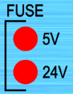

| # | Description | Indication |
| 5V | 5V Fuse Malfunction Indicator | This will normally be OFF. If the 5V fuse is blown, this LED indicator will glow red. |
| 24V | 24V Fuse Malfunction Indicator | This will normally be OFF. If the 24V fuse is blown, this LED indicator will glow red. |
| LSW FUSE | Limit Switch Fuse Malfunction Indicator | This will normally be OFF. If the limit switch is blown, this LED indicator will glow red. |
[9] Power Inputs

| Description | Function |
| 24V 2A DC Connection | Powers components such as the limit switches, relay outputs and spindle control signals. |
| 5V 2A DC Connection | Powers the Teensy®4.1, LED lights and communication devices. |
The E5X MCS requires 2 power inputs to be wired to the following power supplies.
- 24V 2A power supply
- 5V 2A power supply
A dual output switching power supply is recommended for meeting the power requirements of the E5X MCS or alternatively, 2 separate switching power supplies rated at 5V and 24V. The 5V power supply must be connected to the 5V DC terminal and the 24V power supply to the 24V terminal.
The E5X MCS has reverse polarity protection which will illuminate the respective reverse polarity LEDs if power inputs are reversed.
Important
It is important that the power supply outputs are measured with a multi-meter prior to connecting to the E5X. The power inputs must not exceed 24V for the 24V DC input connector and 5V for the 5V DC input connector on the E5X MCS. The onboard circuitry may be irreversibly damaged if the supply voltage exceeds the specified voltage.
![[WM] 2.1 Power Inputs](https://makerhardware.net/wp-content/uploads/2022/12/WM-2.1-Power-Inputs-e1672790466699.png "[WM] 2.1 Power Inputs")
Pro Tip: We highly suggest crimping or soldering the end of your wires for the best connection. To crimp the wires correctly follow the below steps.
- Take the wires and strip the ends using a wire stripping tool.


Click to expand
- Twist the copper strands of each wire gently as shown on the left.


Click to expand
- Place a spade terminal on twisted strands of each wire and crimp using a crimping tool to make a good connection.
4.0 Motor Inputs and Outputs

The E5X MCS has outputs for 5-Axis (+1 slave/clone Axis) motor control. These outputs are accessible via 3 Pin 3.81mm screw terminal connectors.
[12] Motor Outputs

| # | Description | Function |
| X-AXIS | X-Axis Enable, Step and Direction signal output. | Transmits motor control signals to the stepper motor drivers or servo motors. |
| Y-AXIS | Y-Axis Enable, Step and Direction signal output. | |
| Z-AXIS | Z-Axis Enable, Step and Direction signal output. | |
| A-AXIS | A-Axis Enable, Step and Direction signal output. | |
| B-AXIS | B-Axis Enable, Step and Direction signal output. | |
| CLONE | Cloned Axis Enable, Step and Direction signal output. | Transmits motor control signals for dual-axis machines. |
The E5X MCS has external stepper motor driver/servo support for stepper motor drivers and servos with a Step/Direction interface. Each motor can be independently enabled.
The E5X MCS supports a wide range of motors which include but are not limited to Open/Closed loop Stepper Motors and Servos. Each motor type has its benefits, see the list below to check which motors you have or which motors are the best fit for your application.
The E5X MCS allows for more flexible motor control by allowing for external motor driver connectivity and having fully independent driver-enable signals for each axis. Each driver can be enabled and disabled independently via software.
Open Loop Stepper Motors
Open Loop stepper motors are the most common type of stepper motor, requiring an external driver for its four wire configuration.

Closed Loop Stepper Motors
Closed Loop stepper motors have a built in encoder for position feedback with the ability to recover missed steps. They also have alarm outputs to indicate faults in the motor system. The motors generally have a four wire configuration for motor control and subsequent six wire encoder configuration that plug into a external driver.

Servo Motors
Servo Motors motors are high-performance motors that have a built-in encoder for position feedback with the ability to recover missed steps. They also have alarm outputs to indicate faults in the motor system. Servos can come with built-in or external drivers.

The wiring for all motors is nearly identical using the motor drivers’ Step (ST) and Direction (DIR) signal interface. There are two methods of wiring; the Common Anode and the Common Cathode method.
4.1 Motor Driver to E5X Controller- Common Anode Method

| E5X MCS Output | Motor Driver | Description |
| EN | ENA- | Connects the enable signal EN from E5X MCS to the enable pin ENA- on the stepper motor driver. |
| DR | DIR- | Connects the direction signal DIR from E5X MCS to the direction pin DIR- on the stepper motor driver. |
| ST | PUL- | Connects the pulse signal PUL from E5X MCS to the pulse pin PUL- on the stepper motor driver. |
| NC | ENA+ | ENA+, DIR+, PUL+ connected to +V on power supply. |
| NC | DIR+ | |
| NC | PUL+ |
4.2 Motor Driver to E5X Controller – Common Cathode Method

| E5X MCS Output | Motor Driver | Description |
| EN | ENA+ | Connects the enable signal EN from E5X MCS to the enable pin ENA+ on the stepper motor driver. |
| DR | DIR+ | Connects the direction signal DIR from E5X MCS to the direction pin DIR+ on the stepper motor driver. |
| ST | PUL+ | Connects the pulse signal PUL from E5X MCS to the pulse pin PUL+ on the stepper motor driver. |
| NC | ENA- | ENA-, DIR-, PUL- connected to GND on power supply. |
| NC | DIR- | |
| NC | PUL- |
4.3 Clone Axis
The Clone-Axis port and header array clones the movement of another axis for different applications. This is so that both actuators move in sync with one another.
Machines with dual axis actuators of any type use the clone function. The most common use case for Clone-Axis configurations are router style machines with dual Y-Axis actuators.
The clone Axis can be wired using common cathode or common anode method as shown below.

The controller comes with Y-Axis cloned by default, this configuration can be changed by moving 3 shunts to the appropriate headers. Follow the process below to do this:
- Unscrew the M3 Bolts on top of the controller case using a 2.0mm Allen key and gently pull off the case.


Click to expand
- Locate the shunts and gently remove them from STEPY, ENY and DIRY as shown in the highlighted red rectangle below.
")

Click to expand
- Place the removed shunts in the desired axis location, for example STEPB, ENB and DIRB as shown in the images below.


Click to expand
- Ensure that the shunts are correctly seated in their respective locations.
4.4 Motor Alarm Inputs 5/24V
[13] Motor Alarm Status:
The E5X MCS supports motor alarm input digital signals at a 5V or 24V logic level from servo motors and closed-loop stepper motors. Each stepper motor driver or servo motor with an alarm output can be plugged into the E5X MCS. A maximum of 6 driver alarm outputs can be connected to the motion controller.

| # | Description | Indication |
| X-AXIS | X-Axis Motor Alarm Indicator | When a motor alarm is triggered, the red LED indicator will turn on. |
| Y-AXIS | Y-Axis Motor Alarm Indicator | |
| Z-AXIS | Z-Axis Motor Alarm Indicator | |
| A-AXIS | A-Axis Motor Alarm Indicator | |
| B-AXIS | B-Axis Motor Alarm Indicator | |
| CLONE | Clone-Axis Motor Alarm Indicator |
[16] Motor Alarm 5 or 24V

| # | Description | Function |
| X-AXIS | X-Axis Closed Loop Encoder Alarm Signal Input | Closed loop stepper and servo motors send a signal to the specific port when a malfunction is detected in the motor driver. |
| Y-AXIS | Y-Axis Closed Loop Encoder Alarm Signal Input | |
| Z-AXIS | Z-Axis Closed Loop Encoder Alarm Signal Input | |
| A-AXIS | A-Axis Closed Loop Encoder Alarm Signal Input | |
| B-AXIS | B-Axis Closed Loop Encoder Alarm Signal Input | |
| CLONE | Clone-Axis Closed Loop Encoder Alarm Signal Input |
Some Closed Loop motors and Servo systems have alarm outputs that send signals to a controller when an alarm state has been triggered. The E5X MCS utilizes this alarm signal to stop a program or arrest the motion of the machine, preventing damage to the system or workpiece.
NOTE:
To wire the alarm outputs from the alarm source, an external pull-down resistor must be used.
- For 5V systems, use a 2K resistor to pull down the 5V line.
- For 24V systems, use a 10K resistor to pull down the 24V line.

Wiring Sequence:
Wiring the alarm signals involves wiring the positive(+) Alarm pins on the E5X MCS board to the negative(-) Alarm pins on the stepper motor driver or servo. The resistor must be wired between the E5X MCS positive(+) and GND. Furthermore, the E5X MCS negative(-) Alarm pins must be connected to GND. The stepper motor alarm positive(+) pin must be wired to 5/24V power.
| E5X MCS Axis – | Resistor |
| E5X MCS Axis + | GND |
| Stepper Driver + | 24V |
| Stepper Driver – | E5X MCS Axis + |
5.0 Digital Inputs

5.1 Door/Start/Hold/Estop Buttons
[3] Digital
The E5X MCS has 5 assigned CNC-specific digital inputs. The digital inputs are 3.3V and opto-isolated. A momentary button interface is used with these inputs with a 3.3V trigger activating the relevant input when the button is closed.
Normally Open buttons are used for the Digital Inputs.

| # | Description | Function |
| DOOR | Door Open/Shut Sensor | Door alarm for safety enclosures. |
| PROBE | Touch Probe Sensor | Z axis or XYZ axis probing input. |
| ST | Start | Program Cycle Start Button input. |
| HD | Hold | Program Pause/Hold button input |
| ES | Estop | Emergency Stop input. |
| G | Ground | Common Ground. |

Note: ST, HD and ES share a GND pin, while DOOR and PROBE have a dedicated GND pin.

Start
The “START” (ST) button is a normally open momentary button that pulls the SIG pin low when the button is pressed. This starts any G-code program currently loaded in the ioSender software.
For a 2-pin button, wire the GND pin from the E5X MCS to the first pin on the button and wire the SIG pin from the E5X MCS to the second pin on the button.
Please consult the datasheet of the button for wiring instructions.
[26] Hold and E-Stop Status:
The HOLD and ESTOP status LEDs show the status of the Feed Hold and Estop inputs when active or inactive. A button array can be connected to these inputs.

| # | Description | Indication |
| HOLD | Hold Status Indicator | When the HOLD button is pressed, this LED indicator will glow yellow. |
| STOP | E-Stop Status Indicator | When the E-Stop is activated, this LED indicator will glow yellow. |

Hold
The “HOLD” (HD) button is a normally open momentary button that pulls the SIG pin low when pressed. This temporarily pauses the machine function until the “START” button is pressed.
For a 2-pin button, wire the GND pin from the E5X MCS to the first pin on the button and wire the SIG pin from the E5X MCS to the second pin on the button.
Please consult the datasheet of the button for wiring instructions.

E-Stop
The “E-Stop” (ES) button is a Normally Open button that halts any running G-Code program and all motor function in both CNC and manual control mode.
For a 2-pin button, wire the GND pin from the E5X MCS to the first pin on the button and wire the SIG pin from the E5X MCS to the second pin on the button.
Please consult the datasheet of the button for wiring instructions.
[19] Door and Probe
The E5X MCS has inputs for using a probing tool and a door sensor. The types of probes supported are standard 2-wire touch probes and XYZ probes. The PROBE led illuminates when an end mill makes contact with the probe during the probing process.
The door sensor input is used when a machine is placed in an enclosure equipped with a door switch to prevent a user from interacting with the machine while it is in operation. The DOOR led illuminates when the door sensor switch is activated by opening the enclosure door and ceases the machine’s operation.

| # | Description | Indication |
| PROBE | Probe Status Indicator | When the end mill makes contact with the probe, this LED indicator will glow yellow. |
| DOOR | Door Status Indicator | When the machine enclosure door has been opened, this LED indicator will glow yellow. |

Door
The “Door” (DOOR) switch is a normally open switch attached to an enclosure door. When the switch is activated by opening the enclosure door, the controller arrests the motion of the machine until the door is closed and the “Start” (ST) button has been pressed. Generally, mechanical limit switches are used as door sensors.
The switch’s normally open (NO) pin should be wired to the “DOOR” SIG pin of the E5X MCS, and the common (COM) pin should be wired to the “GND” pin of the E5X MCS.

Probe
The E5X MCS supports both generic 2-wire Z-Axis probes and 2-wire XYZ-Axis probes. The wiring sequence is identical for both types of probes.
The “Probe” is a normally open device that is used to zero out the work coordinates before machining starts. The GND pin of the E5X MCS connects to the alligator clip wire of the Probe and the SIG pin of the E5X MCS connects to the Probe plate wire.
5.2 Digital Inputs 5V
[8] Digital Inputs 5V
The E5X MCS has four auxiliary digital inputs that are 5V tolerant with a Schmitt trigger buffer. These can be used for future controller expansion and add-ons like sensors and switches. The firmware will need to be modified from stock to accommodate any custom additions via these pins.

| # | Description | Function |
| D100 | Digital Input 00 | 5V Digital Input Port. |
| D101 | Digital Input 01 | |
| D102 | Digital Input 02 | |
| D103 | Digital Input 03 |


The above image depicts a wiring guide of a digital input with a switch. Similar wiring can be implemented for all digital inputs.
[2] Reset
The Reset button is a momentary button that soft resets the controller. This button is tied to the Emergency Stop switch input logic.
![]()
| # | Description | Function |
| RESET | E5X MCS soft reset | Resets the controller. |
6.0 Digital Outputs

[20,21] Outputs
6 outputs can be used for controlling devices such as relays and solenoids. Of the 6 outputs, 3 of these are dedicated to Dust extraction, Mist and Flood coolant functions while the other 3 are auxiliary outputs noted by AUX00, AUX01 and AUX02 can be used for other functions specified by the user. When any of these outputs are activated, the led indicator will glow to show that the specified output is in use.


| # | Description | Indication |
| Dust | Dust Extraction On/Off Status Indicator | When output is activated, the LED indicator will glow yellow. |
| Mist | Mist Coolant On/Off Status Indicator | |
| Flood | Coolant On/Off Status Indicator | |
| AUX02 | Auxiliary 02 Output On/Off Status Indicator | |
| AUX01 | Auxiliary 01 Output On/Off Status Indicator | |
| AUX00 | Auxiliary 00 Output On/Off Status Indicator |
[7] Digital 24V
The Dust extraction, Mist and Flood Coolant outputs are activated by conventional G-code commands. The other 3 are auxiliary outputs noted by AUX00, AUX01 and AUX02 can be used for other functions such as activating devices and require the use of grblHAL’s extended M-code support.

| # | Description | Function |
| AUX00 | Auxiliary Output 00 | Auxilary Digital outputs for 24V relays of solenoids. |
| AUX01 | Auxiliary Output 01 | |
| AUX02 | Auxiliary Output 02 | |
| FLOOD | Coolant Relay Output | 24V Flood Coolant Output. |
| MIST | Mist Coolant On/Off Signal | 24V Mist Coolant Output. |
| DUST | Dust Extraction (Vacuum) On/Off Signal | 24V Dust Extraction Output. |
The 24V digital outputs are opto-isolated and output 24V 0.5A when activated in software via G-Code or through the G-Code sender. These outputs must be connected to either a Mechanical, Solid State Relay (SSR) or solenoids. The mechanical, SSR relay or solenoid input power requirements must not exceed 24V 0.5A. All digital outputs including auxiliary outputs are active high and their behaviour can be changed in the software to suit your requirements.
NOTE: AUX00, AUX01 and AUX02 can be activated using additional M-codes (see below). The post-processor being used to generate G-code will need to be modified if the user wishes to use these outputs.
| E5X MCS | Relay Module |
| GND | GND input pin |
| SIG | Signal input pin |


Click to expand
# | Description | M-code | Function |
AUX00 | Auxiliary Output 00 | M64 PO = ON M65 PO = OFF | Auxiliary Digital outputs for 24V relays or solenoids |
AUX01 | Auxiliary Output 01 | M64 P1 = ON M65 P1 = OFF | |
AUX02 | Auxiliary Output 02 | M64 P2 = ON M65 P2 = OFF | |
FLOOD | Coolant Relay Output | M8 = ON M9=OFF | Flood Coolant Output |
MIST | Mist Coolant On/Off Signal | M7 = ON M9 = OFF | Mist Coolant Output |
DUST | Dust Extraction (Vacuum) On/Off Signal | M3 = ON M5 = OFF | Dust Extraction Output |
The GND pin from the E5X MCS controller must connect to the GND pin of the mechanical relay. Likewise, the SIG pin from E5X MCS controller connects to the signal input pin of the relay.
7.0 Limit Switch Inputs

Two types of limit switch indicators are present on the E5X MCS; the first set of orange LED indicators display whether the limit switch is in an open state (not activated) and the second set of yellow indicators display whether the limit switch is in a closed state (activated). Mechanical and Inductive switches operating either in a Normally Open or Normally Closed configuration are supported by the E5X MCS. The limit switch logic supported is 24V.

| # | Description | Indication |
| X | X-Axis Limit Switch Status Indicator | When the limit switch is activated, the yellow “CLOSED” LED indicator will activate otherwise the orange “OPEN” LED indicator will remain on. |
| Y | Y-Axis Limit Switch Status Indicator | |
| Z | Z-Axis Limit Switch Status Indicator | |
| A | A-Axis Limit Switch Status Indicator | |
| B | B-Axis Limit Switch Status Indicator |
The E5X MCS controller accepts 24V signal inputs from mechanical, PNP and NPN inductive proximity switches. There are 5 independent limit switch inputs for a 5-axis setup; X,Y,Z,A,B. All limit switch inputs are opto-isolated.
The limit switch inputs are fuse protected against short circuits. If there is a short circuit between the limit switch power and ground terminals, the fuse will blow, protecting the board and switch.

| # | Description | Function |
| X-AXIS | X-Axis Limit Switch Power and Signal Input | Receives a signal from the X-Axis limit switch. |
| Y-AXIS | Y-Axis Limit Switch Power and Signal Input | Receives a signal from the Y-Axis limit switch. |
| Z-AXIS | Z-Axis Limit Switch Power and Signal Input | Receives a signal from the Z-Axis limit switch. |
| A-AXIS | A-Axis Limit Switch Power and Signal Input | Receives a signal from the A-Axis limit switch. |
| B-AXIS | B-Axis Limit Switch Power and Signal Input | Receives a signal from the B-Axis limit switch. |
NOTE: Inductive proximity switches and mechanical switches are wired differently. Take note of the wiring sequence to avoid component damage. Please consult the datasheet of both the mechanical and inductive proximity limit switches before wiring.
7.1 Mechanical Switches


Mechanical Switches trigger when the circuit is completed through a physical mechanism. Mechanical switches can be wired into the E5X MCS controller using either the Normally Open or Normally Closed configurations.
In a Normally Open configuration, the controller reads a low signal (0V) as normal operation and a high signal (24V) as a limit switch trigger.
In a Normally Closed configuration, the controller reads a high signal (24V) as normal operation and a low signal (0V) as a limit switch trigger. The Normally Closed configuration is recommended as the user will be notified when a fault is detected in the wiring, preventing the relevant machine axis from crashing into the machine structure.
NOTE: Observe the wiring diagram below. Incorrect wiring can blow the fuse.
It is recommended to use a shielded 2-core cable to minimise chances of EMI (Electromagnetic Interference) triggering the limit switches. If experiencing EMI (false limit switch triggers), the shield of the 2-core cable must be terminated on one side to the GND terminal on the 24V power supply.


Click to expand
7.2 Inductive Proximity Switches


Click to expand
Inductive proximity switches trigger when a circuit completes electronically. To complete this electronic circuit, the inductive proximity switch needs to come into contact with a metallic surface such as aluminium or steel. Inductive switches perform best when in contact with ferrous metals such as steel.
NOTE:
- Observe the wiring sequence on the inductive proximity switch. Incorrect wiring will damage the inductive sensor.
- Use a 3-core cable to wire in the inductive proximity sensors to the E5X MCS.
- The Inductive proximity switches have a working voltage range. Ensure that your Inductive proximity switch is in the 24V range.
- NPN NC limit switches are recommended for use with the E5X MCS.

| E5X MCS Controller | Inductive Proximity Switch |
| 24V | 24V (BROWN) |
| SIG | Signal (BLACK) |
| GND | GND (BLUE) |
8.0 Toolhead Outputs

The E5X MCS provides various control modes tailored to different tool types. Among the commonly used tools with CNC machines are spindles, lasers and routers.
[22] Spindle Status:
Spindles and Variable Frequency Drives (VFDs) can be controlled by the E5X MCS. The SPINDLE STATUS led indicates when the spindle motor is in use.

| # | Description | Indication |
| SPINDLE STATUS | Spindle On/Off Status Indicator | When the spindle is actively running, this LED indicator will glow blue. |
8.1 5V PWM
[6] 5V PWM

| # | Description | Function |
| PWM | Pulse Width Modulation output. | Sends a 5V PWM signal to drive 5V Compatible devices such as diode lasers. |
The E5X MCS T41 controller can drive diode laser modules or any tools requiring a 5V PWM control input. This output varies the output voltage from 0-5V depending on the value set in the G-code program. See the wiring method below for a typical diode laser connection.
Note:
- Refer to the datasheet/user manual of your laser as connections may vary.
| E5X MCS T41 Terminal | Laser Terminal |
| SIG | TTL+ |
| GND | TTL- |

8.2 Spindle Analog
[5] Spindle Analog Signals

| # | Description | Function |
| 0-10V | 0-10V output signal | Provides 0-10V signal for spindle speed control. This is mapped to the minimum and maximum spindle speeds set in G-code. |
| 4-20mA | 4-20mA output signal | Provides a 4-20mA signal for spindle speed control. This is mapped to the minimum and maximum spindle speeds set in G-code. |
The spindle analog output terminal controls the spindle speed with either a 0-10V or 4-20mA signal. These outputs have a built-in filtering circuit to stabilise the signal output, ensuring stable spindle speeds. The VFD must be configured for either mode of speed operation before use. Consult your manufacturer’s VFD manual for information on how to do so.
0-10V is the more commonly utilised signal for spindle speed control. 4-20mA is commonly used where situations require long cable runs between the VFD and E5X MCS controller to reduce signal loss. 4-20mA signals can offer increased immunity to Electromagnetic interference (EMI) from other devices.
Note: This connection is only recommended if the analog input wiring from the E5X MCS to the VFD is isolated from the high-voltage wiring of the VFD.
0-10V Method:
Connect the 0-10V SIG pin from the E5X MCS to the analog input (AI1) signal pin on the VFD. Connect the 0-10V GND pin from the E5X MCS to the analog ground pin (ACM) on the VFD.
Note: This connection is only recommended if the analog input circuitry of the VFD is isolated from the high-voltage part of the VFD.
| Description | E5X MCS T41 Terminal | VFD Terminal | Function |
Spindle Speed Signal – Voltage | SIG | AI1 | Varies speed of spindle from min to max using Voltage. |
| GND | ACM |
Important
It is essential to check your VFD and Spindle manuals before connecting as incorrect wiring can cause failure.
This instruction set is for the Folinn BD600 VFD, please consult your VFD manufacturer for wiring instructions.

4-20mA Method:
Connect the 4-20mA SIG pin from the E5X MCS to the analog input (AI1) signal pin on the VFD. Connect the 4-20mA GND pin from the E5X MCS to the analog ground pin (ACM) on the VFD.
Note: This connection is only recommended if the analog input circuitry of the VFD is isolated from the high-voltage part of the VFD.
| Description | E5X MCS T41 Terminal | VFD Terminal | Function |
Spindle Speed Signal – Current | SIG | AI2 | Varies speed of spindle from min to max using a 4-20mA current. |
| GND | ACM |
Important
It is essential to check your VFD and Spindle manuals before connecting as incorrect wiring can cause failure.
This instruction set is for the Folinn BD600 VFD, please consult your VFD manufacturer for wiring instructions.

8.3 Spindle Digital
[4] Spindle Digital
The E5X MCS has Spindle Enable and Spindle Direction signal outputs to control the VFD and spindle automatically during jobs.

| # | Description | Function |
| SP-DIR | Spindle Direction | The signal is used to change the spindle direction from clockwise (default) to anti-clockwise. |
| SP-EN | Spindle Enable | The signal is used to turn the spindle on or off. |
The VFD signal inputs are typically pulled high to 12 or 24V and need to be pulled down to control the VFD appropriately.
The E5X MCS Spindle Enable and Spindle Direction Outputs are wired directly to the VFD. These signals pull the VFD start signal pin low, triggering the VFD to turn the spindle on (Spindle Enable) or change the spindle direction (Spindle Direction).
Generally, only Spindle Enable is required to control the VFD, but some applications require direction change from the VFD, therefore requiring Spindle Direction.
If wiring both Spindle Enable and Spindle Direction, a control method called 2-wire control is required for the VFD to determine the correct motor function when the pin logic for the 2 outputs (Spindle Enable and Spindle Direction) are at different levels.
Consult your VFD manual to configure a 2-wire control signal from your spindle to the E5X MCS controller.
| # | Description | E5X MCS T41 Terminal | VFD Terminal | Function |
SP-EN | Spindle Enable | SIG | S1 | The Spindle Enable signal triggers the VFD to start the spindle. |
| GND | GND | |||
SP-DIR | Spindle Direction | SIG | S2 | The Spindle Direction signal triggers the VFD to change the rotational direction of the spindle. |
| GND | GND |

Important
The VFD terminals in your system will vary. Consult your VFD manufacturer regarding the appropriate wiring sequence for your VFD.
9.0 Communication

Communication with the E5X MCS controller can be made via Ethernet or USB. This communication is done using the ioSender G-code sending software to control and configure the machine via the E5X MCS.
[18] Digital
For future expansion, the E5X MCS controller has a serial interface to add peripherals such as pendants and Human Machine Interface (HMI) devices.

| Description | Function |
| RX – | Receiver pin. Receives signal from an external device. |
| TX- | Transmit pin. Transmits signal to an external device. |
| 5V | 5V output power to an external device. |
| GND | Common ground connection |
[1] Communication

| Description | Function |
| Ethernet | Direct communication between the E5X MCS and the computer via Ethernet connection with an RJ45 cable. |
| USB | Communication between the E5X and the computer via USB connection. USB communication can be done via USB A to B cable |
The E5X uses ioSender to communicate with the CNC machine’s components. For more information on ioSender and settings, see chapter 10.0 Software Configuration Guide.
USB Control
Ethernet Control


Click to expand
10.0 Software Configuration Guide
The E5X requires a G-code sending software to control the outputs and execute instructions based on the G-code. Below is the guide for different modes of operation.
10.1 Setup in ioSender
Download ioSender
To interface with the controller, you will need G-Code sending software. There are many types of G-Code senders available, but we highly recommend ioSender. It is a powerful G-Code sender used for CNC control with a feature-rich and easy-to-use interface.
ioSender can be downloaded here. Be sure to download the latest release.
- Locate the downloaded file. By default, it should be in your Downloads folder.
- Unzip the downloaded file and copy the folder to your desktop.
- Open the folder and locate ‘ioSender.exe’. Double-click the file to open it. It will initially launch with the following screen.

Brief Intro to ioSender:
ioSender is the recommended G-code sender for use with the E5X MCS controller. It allows for easy machine configuration and advanced functionality to improve workflow.
The following ioSender Screen will pop up when you run the software. The main aspects of the program have been highlighted for you.

Configuring ioSender:
Before first use, it is recommended to adjust a few parameters of the software. The main adjustments are shown below, highlighted by the green square. After adjusting the parameters, click the Save Settings button highlighted by the red square:

10.2 USB Setup
10.2.1 USB Selection Guide
For USB connectivity, a USB type A to type USB type B cable is required. As USB can be susceptible to EMI from devices such as spindles, it is highly recommended to keep the cable as short as possible and use a USB cable with shielding and Ferrite choke built into the cable as shown below.

Click to expand
The E5X MCS uses a Silicon Labs CP2102 USB UART bridge to communicate with ioSender. To use the USB connection, you will need to install the CP2102 USB drivers. See below for the installation instructions.
- Download and install the CP210x drivers here:
- Extract the file and run:
- CP210xVCPInstaller_x64 if you have a 64-bit computer
- CP210xVCPInstaller_x86 if you have a 32-bit computer
To communicate with ioSender via USB, open ioSender and select the Serial tab. In the Port drop-down box, select the correct port with Silicon Labs CP210x USB to UART Bridge. Please note, your port will likely differ from the one shown in the example.
By default, the Baud rate is set to 115200 bits per second. This value should not be changed as it will affect the E5X MCS performance.
The On connect behaviour should be set to No action.
Selecting Ok will launch ioSender and you will have full access to CNC machine controls.

10.3 Ethernet Setup
The E5X MCS uses a Texas Instrument DP83825I 10/100-Mbps Ethernet PHY transceiver to communicate with ioSender. Ethernet communication is made through a direct connection between the E5X MCS and an ethernet-enabled computer. No switching devices like a router or ethernet switch are required for a direct PC connection.
A standard RJ45 cable is used to make the connection.

Click to expand
The ethernet connection is most recommended as it is highly resistant to EMI. Ethernet cables have twisted pairs that reject interference from external equipment like VFDs and Spindles. The ethernet configuration needs to be made in two places; in ioSender and in the computer’s network settings. The parameters that need to be changed are the following:
E5X MCS Network Parameters:
- IP address
- Gateway
- IP Mode
Computer Network Parameters:
- IP address
- Gateway
Below is the guide for changing these parameters, it is imperative that your network settings are the same as the ones in this guide.
10.3.1 Set up Network on the E5X MCS
Each E5X MCS controller comes pre-flashed with the network settings pre-set. The settings are as follows;
- IP address: 192.168.5.1
- Gateway: 192.168.5.1
- Hostname: GRBL
- IP Mode: Static
If the settings have changed due to a modification to the firmware, the network settings can be set in ioSender in the networking menu. Click on each of the settings and set the parameters as shown above. Click Save after making the changes and restart the controller for the changes to take effect.

10.3.2 Set up Network on the computer
To set up the network connection enter ‘Network Status’ in the Windows Search bar. Click on the View Network Status and Tasks pop-up.

The Network and Sharing Center menu will show. Click on Change adapter settings as highlighted by the green rectangle below.

A list of available networks will now show. Right-click the Ethernet option and select Properties. The Ethernet Properties will show and we will modify these to suit the E5X MCS.

The current Ethernet properties will now show. Left-Click on the Internet Protocol version 4 (IPv4) and select Properties.

Click Use the following IP address checkbox and set the IP Address to the following:
- IP Address: 192.168.5.5
Change the Subnet Mask to the following:
- Subnet Mask: 255.255.255.0
Click the Validate settings upon exit checkbox and then click OK

Close the Ethernet Properties dialogue box.

The ethernet properties have now been set on your computer, please proceed to the following section to configure ioSender communication with E5X MCS controller via ethernet.
10.3.3 Configure ioSender to Communicate via Ethernet with E5X Controller
To launch ioSender in ethernet mode, ensure that the E5X MCS is connected to the computer via the ethernet cable and is receiving power via the 24V and 5V power input connections. Open ioSender and click on the network tab. Check that the port is set to 23 and the IP address is set to 192.168.5.1.

10.4 Machine Configuration
Depending on the type of machine you have, the motor settings will need to change to suit. The settings that affect the performance of motors are the following;
- Steps per mm
- Acceleration
- Maximum Feed rates
- Maximum Travel
- Motor rotation direction
Motor-Specific Settings:
These settings determine the general behaviour of the motors and can be found in the Stepper submenu. After changing the settings click save button.

Axis-Specific Settings:
These settings determine the general behaviour of the motors and can be found in the Axis submenu.
The image below depicts the X-Axis specific settings. You will need to modify the parameters to suit your machine axis requirements and click save button for the changes to take into effect.

10.5 Homing/Homing Direction
Homing is a function that zeros the machine coordinates or reference position of every axis of the machine. This reference can be used alongside job fixtures and work offsets. Homing involves the machine moving towards the location of limit switches, which is user dependent. Homing can be very helpful to improve one’s workflow.
In the Settings: Grbl navigate to the Limits settings and tick the Hard Limits Enable box. This will enable the limit switches which are required to set the machine coordinates.

In the Settings: Grbl under Homing, tick the Homing Cycle Enable checkbox to initiate homing of the machine.
Enabling the homing cycle will enable the machine to be homed when the homing command has been issued to the E5X MCS. See the image below to enable the homing cycle

After enabling the limit switches and homing cycle, click the save button.
In the main menu, clicking Home or entering in $H will see the machine initiate the homing sequence by moving towards the limit switches.

If the machine is not moving towards the limit switches, take note of the axis moving away from limit switch and abort the homing cycle by pressing the red RESET button or if you have a physical button interface connected to the E5X MCS, press the emergency stop button.
In the Settings: Grbl navigate to the Homing menu to change the homing direction settings for the axis that is moving away from the limit switch. Click Save for the changes to take effect.

After changing the homing direction for respective axis, click save button for the changes to take into effect.
11.0 FAQ
11.1 Electromagnetic Interference (EMI)
Electromagnetic Interference, or EMI is electrical interference caused by an outside source, usually from a Spindle/VFD or Plasma setup. The symptoms of EMI may be the following:
- False Limit switch triggers: The limit switches might trigger randomly, making it seem as if the machine has made physical contact with a limit switch when the machine is not in the immediate vicinity of the limit switches.
- Disconnection issues (via USB): The USB connection may disconnect at random, resulting in a loss of communication with the controller and machining progress.
- Stepper motor position drift: Your stepper motor may have ‘position drift’ meaning that the motor will continue to travel slightly even when it is not receiving signals from the controller.
How to rectify common EMI issues:
- Switch from a USB to an Ethernet connection. See Chapter 10.3 Ethernet Setup for the setup guide.
- Route your spindle cable externally to the cable drag chain and cable tie it to the drag chain to separate the high voltage 3 phase power from the low voltage DC power for the motors, limit switches and encoders.
- Change your limit switch configuration from Normally Open (NO) to Normally Closed (NC) to eliminate false triggers. See Chapter 7.0 Limit Switches for further information on wiring.
- Connect an EMI filter to the E5X MCS power supply and motor/servo power supply. Note: A qualified electrician is required to make any modifications to the mains power.
11.2 Fuse Lights
What causes fuses to blow/fuse lights to turn on?
Fuse lights turn on if a fuse is blown. The fuses have been built into the design of the E5X MCS to prevent damage to the board. The main cause of a blown fuse is a short circuit in the system or over-current. Check the wiring corresponding to the blown fuse and make sure that there are no short circuits. For instance, if the limit switch fuse blows, check the wiring for each limit switch, to make sure that the cables are neatly wired in place and there are no shorts between the wires.
How to replace blown fuses?
- Unscrew the 4x M3 button head bolts at the top of the controller case with a 2.0mm Allen key and gently pull the case off.

Click to expand
- Locate the blown fuse and pull it out gently.

Pro Tip: Use a Mini Blade Fuse Puller to remove the blown fuse, which can be found at your local hardware store.


Click to expand
- Replace with a 2A fast-acting mini-blade fuse. Make sure that the fuse is seated correctly in the fuse holder. These mini-blade fuses can be found at your local hardware store.
- Put the case back on and switch the controller to check whether the fuse light is still illuminated.
11.3 Limit Switch Lights

Limit Switches not triggering
- Check to see if the LMSW Fuse light is illuminated. If it is, the fuse is blown and must be replaced. Please refer to Chapter 11.2 Fuse Lights for investigating the cause and replacing a blown fuse.
- Check to see if the limit switch status is Open. If it is in the Open State, it means that there is either a break in the wire or a limit switch is not connected.
- Check the limit switch logic. Normally closed switches do not need inverting in software. If you have Normally Open Switches, ensure that the logic is inverted in the settings. This is done in the Limits submenu under #5 Invert Limit Pins in Settings: GRBL
- Check that the Hard Limits option is enabled. The Hard Limits are your limit switches. See Chapter 7.0 Limit Switches for further information.
- Use the built-in limit switch diagnostic tool in the main menu as shown below:

- Clicking each limit switch should show a trigger in the form of a red square as shown above. If there is no trigger, check your wiring and make sure that your connectors are well seated.
11.4 Why isn’t my Ethernet Connection working?
The reasons why ethernet connection may not be working may be the result of the following issues:
Incorrect Settings:
Check that the IP address and Gateway parameters on both the computer and in ioSender are as per Chapter 10.3 – Ethernet Setup.
Faulty cable:
- The E5X MCS T4.1 uses a standard RJ45 ethernet cable. You can test if the cable works, by plugging your computer directly into your router using an RJ45 cable. If you are getting a valid connection, the ethernet cable is in good working order.
- Make sure the cable is fully seated in the E5X MCS and the computer. Most Ethernet cables have a clip that clicks in place once fully seated. You should hear a “click” sound when connecting the cable.
- If the above test indicated a faulty cable, try a different cable.
11.5 Why is an Axis not cloned?
If your machine has a dual axis that mirrors another axis, you will need to “clone” the driver control signal. is cloned here are two main reasons why an axis would not be cloned:
Check the Shunt installation location:
By default, the shunts are installed in the STEPY, DIRY and ENY headers to clone the Y-Axis. This can be changed to suit your requirements. Check that the cloning shunts are in the correct location.
Unscrew the 4x M3 button head bolts at the top of the controller case with a 2.0mm Allen key and gently pull the case off.
If for example, the B-Axis is to be cloned, the shunts should be in the DIRB, STEPB and ENB locations as shown below.
")
Click to expand
Check the motor driver outputs are in the correct location:
Make sure that the cloned motor has its driver plugged into the Clone Axis port on the E5X MCS using either the Common Cathode/Common Anode method. Check the wiring at the connector end and ensure, that the wire conductor of each coloured wire is sufficiently clamped by the connector terminal. If the coloured insulator is clamped instead, there will not be a transmission of electrical signals to operate the motor, therefore, strip the wire and complete the connection.
Click to expand
11.6 Why is my USB connection not recognized?
Check that the USB drivers are installed:
The E5X MCS requires the Silicon labs CP2102 USB drivers to communicate with the computer via USB. These can be downloaded here.
Right Click the file and unzip the file. Run:
- CP210xVCPInstaller_x64 for 64-bit computers.
- CP210xVCPInstaller_x86 for 32-bit computers.
Try different Ports and USB Cables
If you have multiple ports on your computer, try a different USB port or USB cable. Try another USB type A to USB type B cable.
Please contact Maker Store at [email protected] if the above troubleshooting steps fail to fix the problem.
Credits
Special thanks to:
PRJC – Teensy
The E5X Motion Controller was designed to use the Teensy® 4.1 Development Board as the microcontroller. Maker Store is an authorised distributor of PJRC’s Teensy® 4.1 Development Board. PJRC are the designers, producers and owners of all Teensy brands and logos.
- PRJC Website: https://www.pjrc.com/
- Teensy 4.1: https://www.pjrc.com/store/teensy41.html
The grblHAL community
- Terjeio ioSender – https://github.com/terjeio
- grblHAL Core- https://github.com/grblHAL/core/graphs/contributors
- grblHAL iMXRT1062 Fork – https://github.com/grblHAL/iMXRT1062/graphs/contributors
The Maker Community
Special thanks to our fantastic Maker Community whose feedback helps provide new ideas and innovation for us to design and produce to make available back to the community.