Search the Knowledge Base
OutBack CNC Version 1.1 Mechanical Assembly Instructions

Please note: The number of holes per rail may vary slightly. This means the number of Screws and T-Nuts will also vary. To allow for this we provided 10% extra Screws and T-Nuts for all Linear Rail.
| Item | Description | Quantity |
| 1 | C-Beam (1000 or 1500mm) | 1 |
| 2 | HGR Linear Rail | 1 |
| 3 | M4 Sliding T-Nut | 17 or 25 |
| 4 | M4 x 14mm Socket Head | 17 or 25 |
Insert the M4x 14mm Socket Head through the HGR Rail and thread on the M4 Sliding T-Nut 1/2 a turn. These will be tighten when aligning the Rails.
Repeat this for all Y-Axis HGR Rails.
Slide the HGR Rail Assembly into the top channels of the C-Beam as per the images.
Repeat for both lengths of the Y-Axis.
Pro Tip: Sliding the HGR Rails and Sliding T-Nuts can be difficult, get another person to help you hold the rail straight while sliding the T-Nuts into the C-Beam.

Using the Linear Rail Alignment Tool (Provided with all Outback Kits), align the HRG Linear Rail as shown.
Start at one end, press the tool so it is flush (as in the image) and move down to every second (odd number) screw aligning and tightening as you go. When you reach the end, return to the start tightening the even number screws.
When done, double check your alignment and repeat if necessary. The tool is a guide and aids in alignment and works well if used carefully and checked as you go. For more exact alignment a dial gauge and a datum edge can be used (this process is not covered here).
Pro Tip: Align the hole in the tool above the screw and place your Allen Key through to tighten the screw.

Slide the two HGR Bearings on to the HGR Rails.
Pro Tip: To avoid loosing any ball bearings keep the support that comes with the packaging on the bearing block. When installing the bearing block onto the rail, use the rail to push the plastic support rail out of the block, this ensures the steel balls are under tension and have contact with a rail at all times.

Note: Although the drawing does not depict this, it is best practice to have the grease nipple facing outwards to allow easier access during maintenance.

| Item | Description | Quantity |
| 1 | Y Plate | 1 |
| 2 | M5 x 20mm Socket Head | 4 |
| 3 | Nut Block TR8x8(P2) | 2 |
| 4 | M5 Nylon Lock Nut | 4 |
Attach 2 x Nut Blocks to the inner face of the Y Plate using 4 x M5 20mm Socket Head Screws and 4 x M5 Nylon Nuts. Only loosely tighten these screws so the Nut Blocks can still move slightly. These will be tightened later.
Repeat for both Y Plates.


| Item | Description | Quantity |
| 1 | M4 x 12mm Socket Head | 8 |
Attach the Y Plate to the HGR Bearings using 8 x M4 12mm Socket Head Screws.
Pro Tip: Positioning the HGR Bearings can be tricky, loosely attach one screw to each bearing before doing the remaining screws. When tightening the screws, tighten all screws completely and then loosen them 1/8th of a turn.

This image shows a view looking up from under the plate, bearings and extrusion. Note how the Nut Blocks are inside the two bearings.

Pro Tip: When you tighten the screws, make sure to do in the order indicated:
- top left
- bottom right
- top right
- bottom left
This is a good practice to follow and should be used for most pattern fastenings.

| Item | Description | Quantity |
| 1 | M5 x 8mm Button Head | 24 or 40 |
| 2 | M5 T-Nut | 24 or 40 |
| 3 | Double L Bracket | 6 or 10 |
Attach the Double L Brackets to the under side of the C-Beam Y Axis.
Leave all the bracket loose, as we will tighten after the base 2040 V-Slot is connected.
Do this for both Y Axis.
Pro Tip: Make sure to slide all the T-Nuts into the C-Beam Slot before attaching the brackets. It is best to do the middle brackets first and work outwards.
Note: The drawings shown are for a 1000mm Y Axis with 3 sets (6 Brackets) of Brackets, screws and T-Nuts. The 1500mm version will require 2 more sets - 5 bracket and screw sets in total (i.e., 10 Double L Brackets).


Attach the 2040 Extrusion for the Spoiler Board Base by sliding into the T-Nuts for the Double L Bracket from the previous step.
This is can be difficult and so take your time. It may help to remove the screws from the Double L Brackets and then re-inset them (make sure to do the inner ones first, other wise you may have to undo to add extra T-Nuts into the slots).
Do this for both Y Axis, making sure to orientate everything correctly.
Pro Tip: This step is a good time to check everything is correct, facing the right way and generally looks alright without mistakes.
Note: This is not the final position of the 2040 Spoiler Board extrusion, so tighten so everything is loose but firm (i.e., not wobbling around but also not super tight).


| Item | Description | Quantity |
| 1 | M5 x 16mm Socket Head | 4 |
| 2 | M5 x 20mm Socket Head | 8 |
| 3 | M5 Sliding T-Nut | 4 |
| 4 | Y Axis End Plate | 1 |
| 5 | 2040 Extrusion | 1 |
Attach the Y Axis End Plates (#4) to the Y-Axis Assembly.
Use 4 x M5 x 16mm Socket Head Screws (#1) and 4 x M5 Sliding T-Nuts (#3) to attach the Y End Plate (#4) to the front/back 2040 Base extrusion (#5). Don't tighten as this will be adjusted in later steps.
Attach the Y Assembly to the Y Axis End Plate by resting the Assembly onto the 2040 Base Extrusion and fix using the 8 x M5 x 20mm Socket Head Screws (#2) - these can be tightened.
Repeat for front and back, and again for the other Y Axis.


Once all 4 Y Axis End Plates are attached the build should look similar to the image.
Note: This are still going to be moved around, squared and aligned. So there is no need to tighten everything yet.

| Item | Description | Quantity |
| 1 | TR8x8(P2) x 1070mm | 1 |
| 2 | 8mm Lock Collar | 1 |
| 3 | 688Z Bearing | 1 |
| 4 | F8-16M Thrust Bearing | 1 |
| 5 | Lead Screw Tensioning Nut | 1 |
Push the Y Gantry Assembly to one the back. Insert the TR8x8(P2) Lead Screw (#1) making sure the bearings and collars are in the correct order.

Continue sliding the Lead Screw in. When it connects with the Nut Blocks, rotate the Lead Screw so it 'screws' into and through the two Nut Blocks. You may need to slide the Nut Blocks and screws along the Y Plate screw slots until the Lead Screw and two Nut Bocks find their correct spacing.
Continue until the Lead Screw extends around 100mm out the other side of the Y Plate.

| Item | Description | Quantity |
| 1 | TR8x8(P2) x 1070mm | 1 |
| 2 | 8mm Lock Collar | 1 |
| 3 | 688Z Bearing | 1 |
| 4 | F8-16M Thrust Bearing | 1 |
| 5 | Lead Screw Tensioning Nut | 1 |
Push the Y Gantry and Lead Screw to the front and guide the Lead Screw through the front Y End Plate. Make sure to thread the Lead Screw with the 8mm Lock Collar (#2) and 688Z Bearing (#3).
Then thread the F8-16M bearing (#4) and screw the Lead Screw Tensioning Nut (#5) onto the end. Just screw it on enough so the Lead Screw is just flush with the face. It will be tightened later.

| Item | Description | Quantity |
| 1 | M5 x 65mm Socket Head | 4 |
| 2 | Stepper Motor | 1 |
| 3 | Motor Spacer | 4 |
| 4 | Coupler 8 - 8mm | 1 |
Making sure the 688z and F8-16M Bearings and 8mm Lock Collars are correctly positioned, attach the 8-8mm Jaw Coupler (#4) to the Lead Screw.
Thread the 4 x M5 x 65mm Socket Head (#1) screws through the Stepper Motor (#2) and 4x Motor Spacers (#3). Align the Motor shaft with the Coupler (#4) and tighten the 4 M5 x 65mm Socket Head (#1) screws.
Note: It is recommend that the Motor Spacers (#3) are mounted horizontally (as in the image) to make cabling and connecting easier at a later stage.


| Item | Description | Quantity |
| 1 | C-Beam | 1 |
| 2 | 4040 V-Slot | 1 |
| 3 | M5 x 8mm Button Head | 12 or 20 |
| 4 | 90 degree Angle Corner Connector | 6 or 10 |
| 5 | T-Nut | 12 or 20 |
Using the 90 Degree Corner Brackets(#4), M5 x 8mm Button Head (#3) screws and M5 T-Nuts (#5) attach the 4040 V-Slot (#2) to the X Axis C-Beam (#1).
For 1000mm X Axis Use:
- 3 x 90 Degree Corner Brackets on top
- 3 x 90 Degree Corner Brackets on bottom
For 1500mm X Axis Use:
- 5 x 90 Degree Corner Brackets on top
- 5 x 90 Degree Corner Brackets on bottom
Pro-Tip: Use a straight edge to align the ends of the C-Beam and 4040. It is important that they are flush at both ends. If not then sand or file gently the piece that is longer.


Please note: The number of holes per rail may vary slightly. This means the number of Screws and T-Nuts will also vary. To allow for this we provided 10% extra Screws and T-Nuts for all Linear Rail.
| Item | Description | Quantity |
| 1 | M4 x 14mm Socket Head | 34 or 50 |
| 2 | HGR Linear Rail | 2 |
| 3 | M4 Sliding T-Nut | 34 or 50 |
Insert the M4x 14mm Socket Head through the HGR Rail and thread on the M4 Sliding T-Nut 1/2 a turn. These will be tighten when aligning the Rails.
Repeat this for the other X Axis HGR Rails.
Slide the HGR Rail Assemblies into the channels of the C-Beam as per the images.
Pro Tip: Sliding the HGR Rails and Sliding T-Nuts can be difficult, get another person to help you hold the rail straight while sliding the T-Nuts into the C-Beam.

Using the Linear Rail Alignment Tool (Provided with all Outback Kits), align the HRG Linear Rail as shown.
Start at one end, press the tool so it is flush (as in the image) and move down to every second (odd number) screw aligning and tightening as you go. When you reach the end, return to the start tightening the even number screws.
When done, double check your alignment and repeat if necessary. The tool is a guide and aids in alignment and works well if used carefully and checked as you go. For more exact alignment a dial gauge and a datum edge can be used (this process is not covered here).
Pro Tip: Align the hole in the tool above the screw and place your Allen Key through to tighten the screw.


Slide the four HGR Bearings on to the HGR Rails.
Pro Tip: To avoid loosing any ball bearings keep the support that comes with the packaging on the bearing block. When installing the bearing block onto the rail, use the rail to push the plastic support rail out of the block, this ensures the steel balls are under tension and have contact with a rail at all times.

Note: Although the drawing does not depict this, it is best practice to have the grease nipple facing outwards to allow easier access during maintenance.


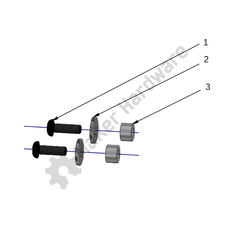
| Item | Description | Quantity |
| 1 | M5 x 45 Button Head | 4 |
| 2 | X Axis Plate | 1 |
| 3 | Drive Nut Spacer | 2 |
| 4 | Nut Block TR8x8(P2) | 2 |
| 5 | M5 Nylon Lock Nut | 4 |
Attach the Nut Spacer (#3) and Nut Block (#4) to the X Axis Plate (#2) using the 4 x M5 x 45 Button Head (#1) screws and the M5 Nylon Lock Nuts (#5).
Tighten so that they are firm but still loose and can be adjusted.

| Item | Description | Quantity |
| 1 | M5 Nylon Lock Nut | 4 |
| 2 | Nut Block TR8x8(P2) | 2 |
| 3 | Drive Nut Spacer | 2 |
| 4 | X Axis Plate | 1 |
| 5 | M5 x 45mm Low Profile | 4 |
| 6 | M4 x 10mm Button Head | 16 |
Using the M4 x 10 Button Head (#6) screws attach the X Axis Plate to the four HGR15 Bearings.
Pro Tip: Positioning the HGR Bearings can be tricky, loosely attach one screw to each bearing before doing the remaining screws. When tightening the screws, tighten all screws completely and then loosen them 1/8th of a turn.

Pro Tip: When you tighten the screws, make sure to do in the order indicated:
- top left
- bottom right
- top right
- bottom left
This is a good practice to follow and should be used for most pattern fastenings.

Slide the gantry to one end and tighten all four HGR bearing screws. Slide the gantry to the other end and make sure there is smooth motion along the entire length. If it gets stiffer or jammed while moving to along the rails, check the spacing of the HGR Rails and try again.
If it is still stiff or jams, us the Alignment Tool on the bottom rail and leave the top rail loose. Move the gantry to one end, making sure the bearings are screwed to the X Axis Plate firmly, then tighten the end most screw on the rail. Slide the gantry to the other end and tighten the other end most screw. Move to the middle and tighten the screw closest to the gantry. Now test again. The gantry should slide smoothly along the entire length.
If the gantry still jams, repeat the above until it runs smooth. The vast majority of problems of stiff gantries is because of incorrect alignment. Be patient, it can take some time to get the alignment correct.
Pro-Tip: The best way to get smooth gantries is to use a datum. Spend time, and use the Alignment Tool, to make sure the bottom HRG rail is correctly aligned on the C-Beam, and use that as the datum for the top HGR Rail and gantry/bearings.

| Item | Description | Quantity |
| 1 | M5 x 8mm Button Head | 6 |
| 2 | M5 x 12mm Button Head | 6 |
| 3 | 90 degree Angle Corner Connector | 6 |
| 4 | M5 T-Nut | 6 |
Using the M5 x 8mm Screws, attach the 90 degree Angle Corner Connectors to the C-Beam and the 4040 Support. Leave them all loose but firm and not sliding around.
Align the X Axis up to the Y Plate and using the M5 x 12mm screws attach the X Axis to the Y Plate.
Do this for both sides.
Pro-Tip: Get something or someone to support the other end of the X Axis while positioning the X Axis and the Y Plate.

Note the location of the 6 x 90 degree Angle Corner Connectors.

| Item | Description | Quantity |
| 1 | M5 x 20mm Socket Head | 8 |
Use the eight M5 x 20mm (#1) screws to secure the X Axis to the Y Plate.
Repeat on both sides.
Tighten all the screws for the XY Assembly (plate screws and brackets).

| Item | Description | Quantity |
| 1 | Lead Screw Tensioning Nut | 2 |
| 2 | F8-16M Thrust Bearing | 2 |
| 3 | 688Z Bearing | 2 |
| 4 | 8mm Lock Collar | 2 |
| 5 | Coupler 8 - 8mm | 1 |
| 6 | Motor Spacer | 4 |
| 7 | Stepper Motor | 1 |
| 8 | M5 x 60mm Socket Head | 4 |
| 9 | Precision Shim – 10 x 5 x 1mm | 4 |
Using the same process as for the Y-Axis, insert the Lead Screw through the Y Plates.

Continue sliding the Lead Screw in. When it connects with the Nut Blocks, rotate the Lead Screw so it 'screws' into and through the two Nut Blocks. You may need to slide the Nut Blocks and screws along the Y Plate screw slots until the Lead Screw and two Nut Bocks find their correct spacing.
Continue until the Lead Screw extends around 100mm out the other side of the Y Plate.
Finish by attaching the Stepper Motor (#7) as in the same way as the Y Axis above.


| Item | Description | Quantity |
| 1 | 2080 V-Slot 250mm | 1 |
| 2 | MGN15 Rail | 2 |
| 3 | M3 Sliding T-Nut | 2 |
| 4 | M3 x 10mm Cap Head | 3 |
Following the same process as for the X Axis, attach and align the MGN12 Rail (#2) onto the 2080 V-Slot (#1).
Use the Alignment Tool when aligning the MGN onto the 2080.

Slide the four MGN Bearings on to the MGN Rails.
Pro Tip: To avoid loosing any ball bearings keep the support that comes with the packaging on the bearing block. When installing the bearing block onto the rail, use the rail to push the plastic support rail out of the block, this ensures the steel balls are under tension and have contact with a rail at all times.
Note: As in the drawing have the grease nipple facing upwards to allow for greater Z Axis travel.

| Item | Description | Quantity |
| 1 | M3 x 10mm Button Head | 16 |
| 2 | M5 x 16mm Socket Head | 2 |
| 3 | Nut Block TR8x8(P2) | 1 |
| 4 | M5 Nylon Lock Nut | 2 |
Attach the Nut Block TR8x8(P2) (#3) to the Z Plate using the M5 x 16mm (#2) screws and the M5 Nuts (#4).
Secure the Z Plate to the MGN Bearings following the same process as for the X Plate to HGR Bearings above.
Note: Make sure the Z Plate is correctly orientated on teh MGN Bearings as per drawings.


| Item | Description | Quantity |
| 1 | M5 x 15mm Low Profile | 4 |
| 2 | Z End Plate | 1 |
Attach the Z End Plate (#2) to the 2080 V-Slot using the 4 x M5 x 15mm Low Profile (#1) screws.

Repeat for the other end.

| Item | Description | Quantity |
| 1 | 688Z Bearing | 2 |
| 2 | 8mm Lock Collar | 2 |
| 3 | Coupler 8 - 8mm | 1 |
| 4 | Motor Spacer | 2 |
| 5 | Stepper Motor | 1 |
| 6 | M5 x 65mm Socket Head | 4 |
Using the same process as for the X and Y Axis, insert the Lead Screw through the Z End Plates.

Continue sliding the Lead Screw in. When it connects with the Nut Block, rotate the Lead Screw so it 'screws' into and through the two Nut Block.
Continue until the Lead Screw extends around 100mm out the other side of the Z End Plate.
Finish by attaching the Stepper Motor (#5) as in the same way as the X Y Axis above.

")
| Item | Description | Quantity |
| 1 | Shim 10x5x1 | 4 |
| 2 | M5 x 20mm Socket Head | 4 |
Using the four Shims (#1) and four M5 x 20mm Socket Head (#2) screws attach the Z Assembly to the X Plate.

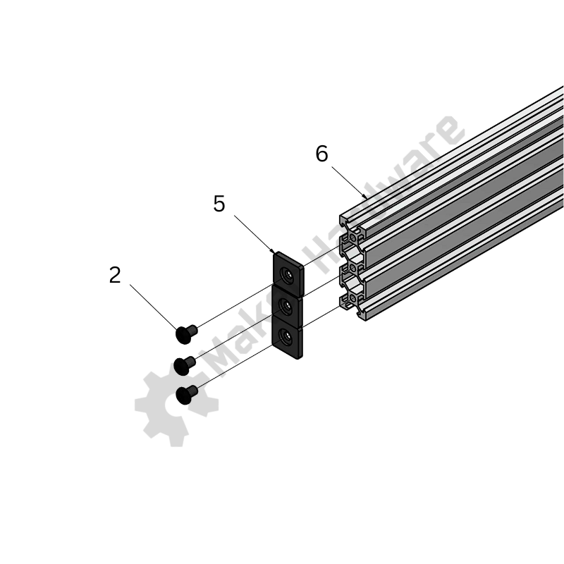
Step1: Slide 2x Sliding T-Nut into the lower groove of 2040 V-Slot 1000/1500mm, one on each end. Attach 2x End Cap - 2040 to 2040 V-Slot 1000mm, one on each end, using 4x M5 x 8 Button Head. See the image on the right.

Step 2: Attach 2x 90 degree Angle Corner Connector, one on each end of 2040 V-Slot 1000/1500mm using 2x M5 x 8 Button Head, as shown in the image on the right.
Step 3: Using 2x M5 x 8 Button Head, attach the above assembly to the 2040 V-Slot Spoiler Board Extrusion. See the images below for reference.


X-Axis:
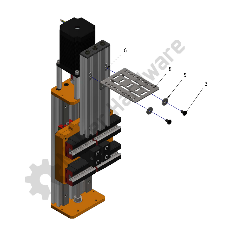
Step 1: Slide 1x Slot Washer and 1x (M5 x 5 Spacer) onto 1x (M5 x 16 Button Head Screw ) in the said order. Repeat the same for the other M5 x 16 Button Head Screw. See the image on the right.
Step 2: Insert the above screw assemblies into the top holes of X-Axis plate as shown in the image on the right. Don't tighten the screws completely.

Step 3: Attach 3x End Cap 2020 to the 2060 V-Slot 180mm of the above assembly using 3x (M5 x 6 Button Head Screws).
Step 4: Slide the above 2060 V-Slot 180mm with the End Caps attached onto the M5 Button Head Screws 16mm attached to the X-Axis Plate and align the holes of the V-Slot with the heads of screw heads. See the images below for reference.
Step 5: Tighten the M5 Button Head Screws 16mm via the holes using an Allen Key. See the images below.


Y-Axis:
Step 1: Slide 2x Sliding T-Nut into the lower groove of 2060 V-Slot 1000/1500mm, one on each end. Attach 6x End Cap - 2020 to 2060 V-Slot 1000mm, three on each end, using 6x M5 x 8 Button Head. See the image on the right.

Step 2: Attach 2x 90 degree Angle Corner Connector, one on each end of 2040 V-Slot 1000/1500mm using 2x M5 x 8 Button Head, as shown in the image on the right.
Step 3: Using 2x M5 x 8 Button Head, attach the above assembly to the 2040 V-Slot Spoiler Board Extrusion. See the images below for reference.
The assembly will look similar to the one in Chapter 4.1, the only difference is the 2060 V-Slot extrusion in place of 2040 V-Slot extrusion.


For simplification purposes, the CDC mounting process has been divided into two parts:
X-Axis:
Step 1: Insert 2x M5 Spring Loaded Tee Nut into the outer grooves of 2060 180mm V-Slot, as shown in the image on the right.
Step 2: Slide 2x Slot Washer- 15 x 5 x 2mm onto 2x M5 Button Head Screws 8mm (one on each screw).
Step 3: Line up the CDC Mounting Bracket slots with the X-Axis 2060 180mm V-Slot Tee Nuts top as shown in the image and insert the M5 Button Head Screws 8mm with washers attached into the slots of the bracket and the Tee Nuts
Step 4: Tighten the the screws to secure the assembly.
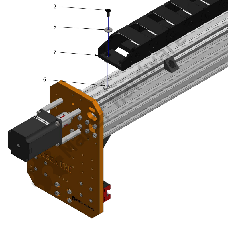
Step 5: Connect one of the CDC Ends to the X-Axis C-Beam extrusion by placing an M5 Spring Loaded Tee Nut into the outer groove of X-Axis C-Beam extrusion. Line up one of the CDC Ends hole with the Tee Nut.
Step 6: Place 1x Slot Washer onto the lined up hole of the CDC and insert 1x M5 Button Head Screw 12mm. Tighten the screw using an Allen Key to secure the assembly. See the image on the right.
Step 7: Take the other CDC End and align the holes with the slots of the CDC Mounting Bracket, as shown in the image.
Pro Tip: Ensure the CDC is straight in reference to the other attached CDC End. Adjust the mounting position on the CDC Mounting Bracket by using different slots.
Step 8: Place 2x Slot Washers onto the lined up holes (one on each hole) of the CDC and insert 2x M5 Button Head Screws 16mm.
Step 9: Tighten the above assembly using 2x Nylon Insert Hex Locknut.
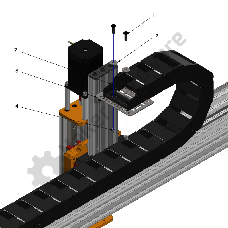
Y-Axis:
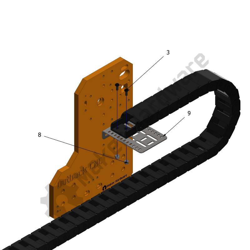
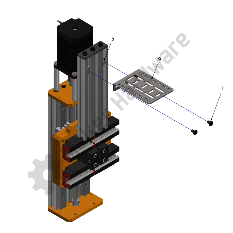
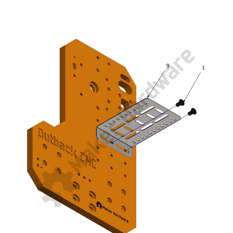
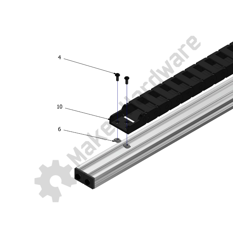
Step 1: Line up the CDC Bracket Mounting Slots with the top holes of the Y-Axis plate, as shown in the image.
Step 2: Slide 2x Slot Washers onto 2x M5 Button Head Screws 16mm (one on each screw) and insert the screws into the holes which are aligned with the tapped holes of X-Axis V-Slots. Tighten the screws to secure the assembly.
Step 3: Insert 2x M5 Spring Loaded Tee Nuts into the outer grooves of the 2060 V-Slot.
Step 4: Line up the CDC End holes with the Tee Nuts. Place 2x Slot Washers onto the aligned holes of CDC and insert 2x M5 Button Head Screws 12mm through the same into the Tee Nuts.
Step 5: Tighten the screws to secure the above assembly.
Step 6: Place the other CDC End onto the Mounting Bracket and line up the CDC mounting holes with slots of CDC Mounting Bracket, as shown in the image.
Pro Tip: Ensure the CDC is straight in reference to the other attached CDC End. Adjust the mounting position on the CDC Mounting Bracket by using different slots.
Step 7: Place 2x Slot Washers onto the aligned holes of CDC and insert 2x M5 Button Head Screws 16mm through the same holes and slots of the Mounting Bracket.
Step 8: Tighten the above assembly using 2x Nylon Insert Hex Locknuts.
For simplification purposes, the CDC mounting process has been divided into two parts:
X-Axis:
Step 1: Insert 2x Drop In Tee Nut M5 into the outer grooves of 2060 V-Slot 180mm.
Step 2: Slide one of the Tee Nuts to the desired position and line up the CDC Mounting Bracket slot with the Tee Nut. Using 1x M5 Low Profile Screws 8mm attach the CDC Mounting Bracket to the Tee Nut in the groove.
Step 3: Repeat the above step for the second Tee Nut. This will attach the CDC Mounting Bracket to the 2060 180mm V-Slot firmly.
Step 4: Connect one of the CDC Ends to the X-Axis C-Beam extrusion by placing 2x Drop In Tee Nut - M4 into the outer groove of the X-Axis C-Beam extrusion. Line up the CDC End holes with the Tee Nuts.
Step 5: Insert 2x M4 Button Head Screw 8mm into the holes and Tee Nuts and tighten using an Allen Key.
Step 6: Place the other CDC End onto the CDC Mounting Bracket and align the holes of the same with slots of the CDC Mounting Bracket, as shown in the image.
Pro Tip: Ensure the CDC is straight in reference to the other attached CDC End. Adjust the mounting position on the CDC Mounting Bracket by using different slots.
Step 7: Insert 2x M4 Button Head Screws 10mm into the CDC End holes through the aligned CDC Mounting Bracket slots.
Step 8: Tighten the above assembly using 2x Nylon Insert Hex Locknut M4.
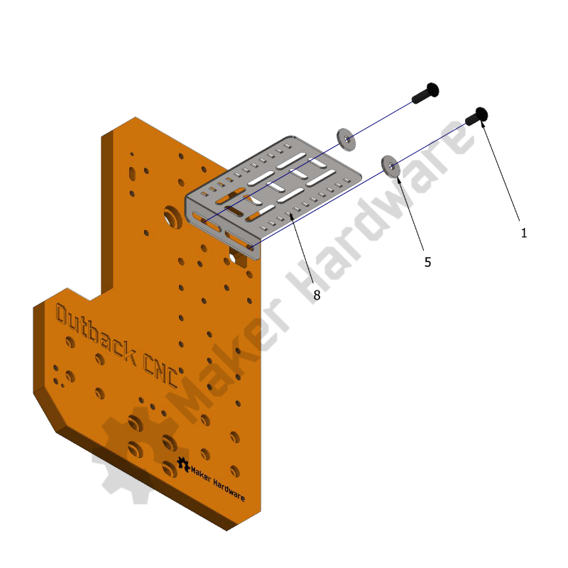
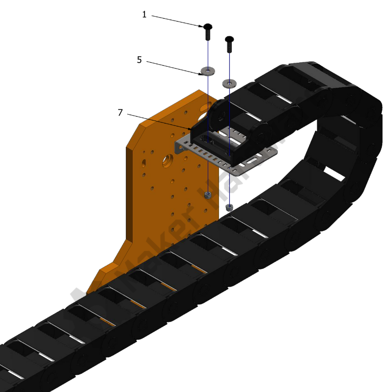
Y-Axis:
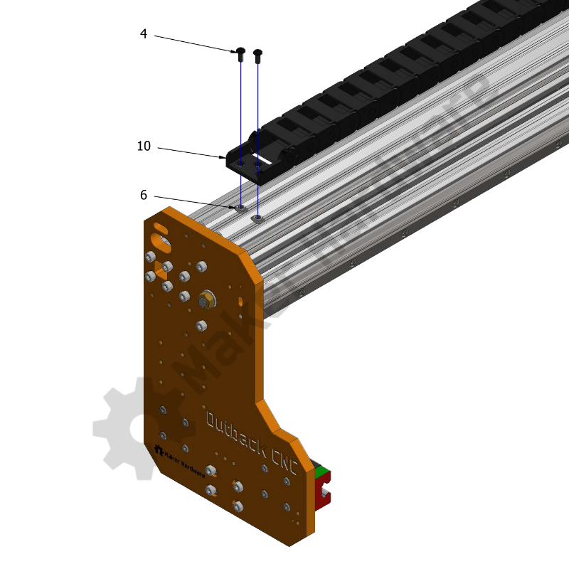
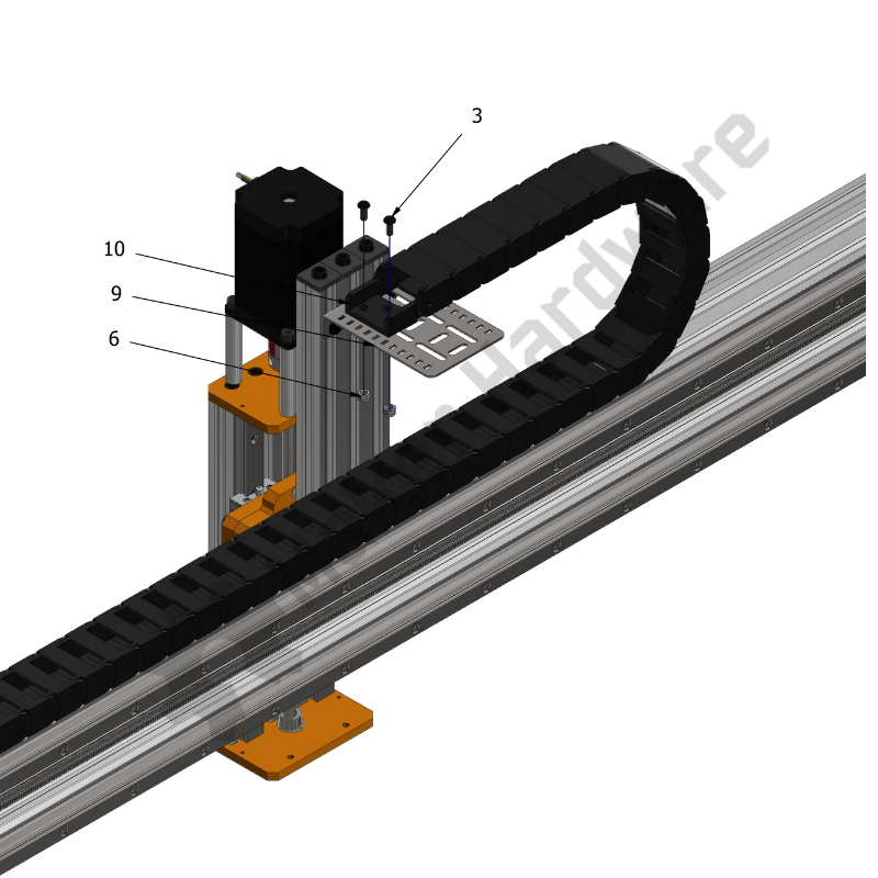
Step 1: Line up the CDC Bracket Mounting Slots with holes of the Y-Axis plate, as shown in the image.
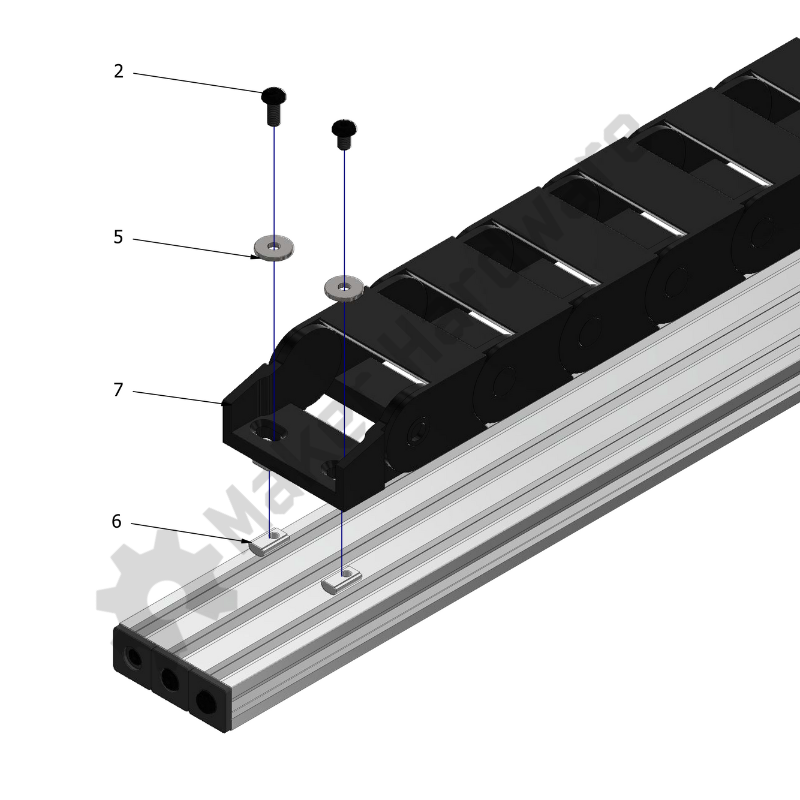
Step 2: Insert 2x M5 Low Profile Screws 8mm into the slots and through the aligned holes.
Step 3: Connect one of the CDC Ends to the 2040 extrusion by placing 2x Drop In Tee Nut - M4 into the grooves of the 2040 extrusion. Line up the CDC End holes with the Tee Nuts.
Step 4: Insert 2x M4 Button Head Screw 8mm into the holes and Tee Nuts and tighten using an Allen Key.
Step 3: Place the other CDC End onto the CDC Mounting Bracket and line up the CDC Mounting holes with slots of CDC Mounting Bracket, as shown in the image.
Pro Tip: Ensure the CDC is straight in reference to the other attached CDC End. Adjust the mounting position on the CDC Mounting Bracket by using different slots.
Step 4: Insert 2x M4 Button Head Screws 10mm through the same holes and slots of the CDC Mounting Bracket.
Step 5: Tighten the above assembly using 2x Nylon Insert Hex Locknuts M4.