
Search the Knowledge Base
Transmitting BME680 sensor readings to an LCD display using a 2 node CAN network
Tutorial Aim:
The aim of this project is to develop a robust environmental monitoring system using two Arduino microcontrollers connected via CAN bus. The system will consist of:
- Transmitter Unit: An Arduino equipped with a BME680 sensor and an MCP2515 CAN bus module. The BME680 sensor will measure environmental data including temperature, humidity, pressure, and air quality. This data will be transmitted over the CAN bus.
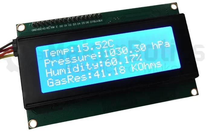
- Receiver Unit: An Arduino connected to a 20×4 LCD display and an MCP2515 CAN bus module. This unit will receive the environmental data from the transmitter unit via the CAN bus and display the real-time readings on the LCD screen.
This project aims to demonstrate the effective use of CAN bus for reliable, real-time data transmission in a sensor network, highlighting the advantages of using a message-based communication protocol for environmental monitoring applications.
Introduction:
The Controller Area Network (CAN bus) is a communication protocol that allows microcontrollers and devices to communicate with each other without a central host computer. It’s especially popular in automotive and industrial applications, but you can also use it with Arduino for various projects.
Key Concepts:
- Communication Protocol: CAN bus is a way for different parts of a system to send messages to each other. It’s like a chat room where everyone can talk, but only one person (or device) talks at a time.
- Differential Signaling: CAN bus uses two wires, CAN_H (high) and CAN_L (low), to send signals. This helps reduce noise and ensures reliable data transmission even in noisy environments.
- Message-Based: Instead of sending data to specific addresses, CAN bus messages have identifiers. These identifiers indicate the priority and type of data. Each device (or node) listens to all messages and processes only those that are relevant.
The modules used in this tutorial communicate using the CAN 2.0B protocol
Requirements:
This tutorial makes use of the Arduino IDE 2.3
- Arduino IDE
- 2 x Arduino (Compatible) UNO R3 with USB cable
- BME680 Environmental Sensor Module
- Breadboard
- 18 x FM Jumper Wires
- 6 x MM Jumper Wires
- LCD 2004 (20X4) – I2C – Blue Display
- 2 x MCP2515 CAN Bus Module with TJA1050 Receiver
Pin Layout:
Sender Pinout:
This pinout is for the sending/transmitting Arduino. This will have the MCP2515 CANBUS module and MBE680 sensor module and will transmit the sensor values.
Receiver with MCP2515:
| Arduino | MCP2515 |
| 5V | VCC |
| GND | GND |
| 2 | INT |
| 10 | CS |
| 11 | SI |
| 12 | SO |
| 13 | SCK |
Sender with BME680 Sensor:
| Arduino | BME680 |
| 3V3 | VCC |
| GND | GND |
| A4 | SDA |
| A5 | SCL |
Receiver Pinout:
This pinout is for the receiving Arduino. This will have the MCP2515 CANBUS module and LCD to display the transmitted data.
Receiver with MCP2515:
| Arduino | MCP2515 |
| 5V | VCC |
| GND | GND |
| 2 | INT |
| 10 | CS |
| 11 | SI |
| 12 | SO |
| 13 | SCK |
Sender with LCD Display:
| Arduino | LCD Display |
| 3V3 | VCC |
| GND | GND |
| A4 | SDA |
| A5 | SCL |
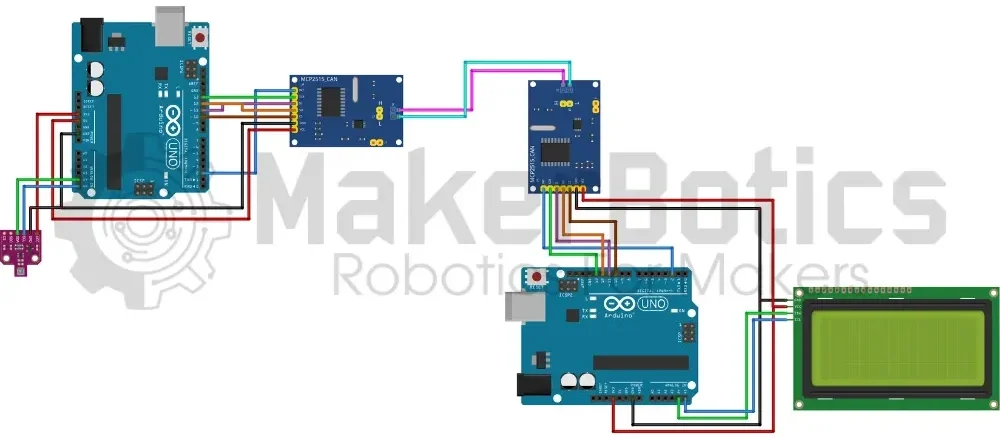
Wiring diagram:
Wire the components according to the circuit diagram shown above.
Code Walk Through:
For the sensor data to be transmitted & received, we’ll need to code one Arduino UNO to be the transmitter, and the other to be the receiver. This code is provided in the following 2 sections.
CAN Transmitter Code Walk Through:
Libraries & Variables:
To access & use the BME680 sensor we include the Adafruit_BME680.h library by Adafruit. As the sensor uses I2C protocol to communicate with microcontrollers the Wire.h library is also needed. For information about the Adafruit_BME680.h library: https://github.com/adafruit/Adafruit_BME680
For the CAN network we use the CAN.h library by Sandeep Misty. For more information about the CAN.h: https://github.com/sandeepmistry/arduino-CAN
We define each readings message id so that we can distinguish between transmitted readings. We also create global variables to store the sensor readings for easier access and to safeguard against invalid values caused by failed sensor readings.
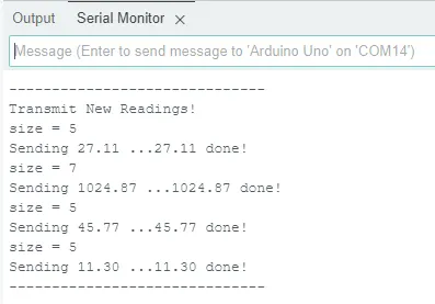
Serial monitor output:
CAN Receiver Code Walk Through:
Libraries & Variables:
To access & use the LCD display we include the LiquidCrystal_I2C.h library by Frank de Brabander. As the display uses I2C protocol to communicate with microcontrollers the Wire.h library is also needed. For information about the LiquidCrystal_I2C.h library: https://github.com/johnrickman/LiquidCrystal_I2C
For the CAN network, we use the CAN.h library by Sandeep Misty. For more information about the CAN.h: https://github.com/sandeepmistry/arduino-CAN
We define each reading’s message ID to distinguish between transmitted readings. The maximum CAN message length in bytes is also defined. We create an LCD variable with the I2C address of 0x27, 20 columns & 4 rows. Please note that I2C addresses may vary for each LCD display, so please double-check your I2C address before continuing. This can be done using the i2c_scanner example in the Wire.h library.
The sensor readings are stored as global variables for easier access.
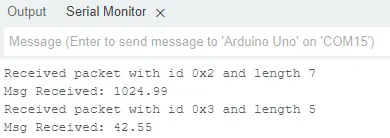
Receiver serial monitor output:
Each message’s information – id, size & content – is displayed on the serial monitor for potential debugging & monitoring purposes.
Full Transmitter Code:
Full Receiver Code:
Flashing and displaying the data:
- Connect the Arduino controllers to the computer separately.
- Flash the sender code onto the Arduino connected to the BME680 & flash the receiver code onto the Arduino connected to the LCD display.
- After flashing both systems successfully, connect both arduino controllers to the computer or use a portable 5VDC power source to power the system and display the sensor data.
Downloadable Content:
Please find this tutorial’s code on our GitHub page.