
Search the Knowledge Base
Teensy 4.1 INA226 Current Sensor Tutorial
Tutorial Aim:
The goal of this tutorial is to read and display the INA226 sensor output using a Teensy 4.1
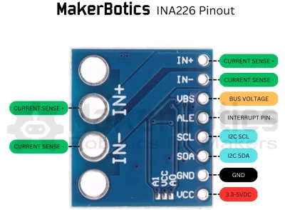
The INA226 is a precision dual-function voltage and current sensor that is designed to accurately measure both the voltage and the current flowing through a shunt resistor. The device is commonly used in a variety of power management and monitoring applications.
Requirements:
This tutorial makes use of the Arduino IDE & the Arduino Starter Pack
- Arduino IDE v.2.21 or later
- Teensy 4.0/4.1 microcontroller
- INA226 Current Sensor
- 6 Male to Female Jumper Wires
- 3 Male to Male Jumper Wires
- Breakout Board
- 1 LED
- 80Ohm Resistor
| Sensor Pins: | Teensy Pins: |
| GND | GND |
| VCC | 5V |
| SDA | 18 |
| SCL | 19 |
Setup:
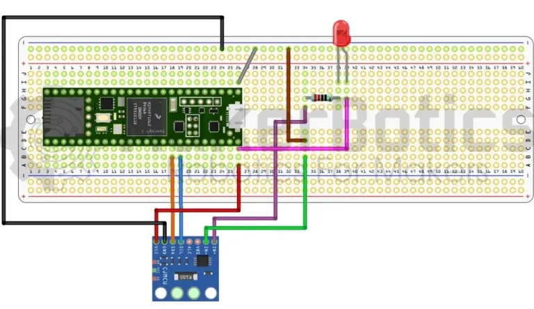
Refer to the image below for wiring.
- Connect the current sensor’s SDA pin to pin 18 & SCL pin to pin 19 on the Teensy 4.1 using the FM jumper wires.
- Open Arduino IDE
- Plug in the Teensy 4.1 to the computer
Code Walk Through:
Libraries:
To access & use the current sensor we include the INA226.h library by Rob Tillaart. As the current sensor uses I2C protocol to communicate with microcontrollers the Wire.h library is also needed.
For information about the INA226.h library by Rob Tillaart please visit his Github.
Initiating the sensor:
Using the INA226 library we can initialize the sensor with our I2C address (0x40), test if the sensor begins & set the max current shunt.
To avoid sensor connection issues, please ensure that you have the correct I2C address. This can be checked using i2c_scanner example found in the Wire library.
Gathering the sensor data:
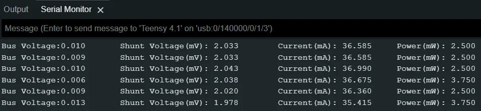
We can gather and display the sensor’s bus voltage, shunt voltage, current, & power readings every 2 seconds.
Current Sensor Code:
Entire tutorial code for your reference:
Serial Output:
The sensor readings are displayed on the serial monitor.
Downloadable Content:
Please find this tutorial’s code on our Github page.
Credits:
- Arduino
- The Arduino Community
- The STEM Community