
Search the Knowledge Base
Teensy 4.1 Colour Detection Tutorial
Tutorial Aim:
The aim of this tutorial is to use a TCS3472/TCS34725 colour sensor to identify RGB values & determine the predominant colour using a Teensy 4.1 microcontroller.
Introduction:
The TCS3472 colour sensor is a popular colour sensor used for colour recognition. The sensor features a high-sensitivity colour-sensing chip, a wide colour-sensing range, light intensity measurement and a built-in IR-blocking filter. This makes the TCS3472 an ideal colour-sensing solution for use under variable lighting conditions. The TCS3472 can generate an interrupt signal if light sensed by the module exceeds or drops below a programmed threshold value.
The TCS3472 colour sensor has a wide range of applications which includes, colour-oriented pick and place devices, RGB LED backlight controls and colour object tracking.
Key Concepts:
- IR Blocking Filter: The IR blocking filter gets rid of the infra red component of the incoming light to ensure that only the visible portion of the light gets measured. The measuring elements consist of four light sensitive photodiodes – red, blue, green and clear. Again, from the datasheet, the spectral response of the photodiodes is included,
- Photodiodes: Produces a signal proportional to the intensity of the specific wavelength of light impacting them, provided that this light is within their wavelength sensitivity range. For example, if incoming light is blue, the blue photodiode will produce a signal, whereas the red and green will not “see” this light and will produce no signal. White light (which contains all colors) will result in a signal from every photodiode. The clear diode reacts to all wavelengths across the visible spectrum.
- Calculating Light Reading: The signals from the various diodes are then fed into a ADC and are added up cumulatively over a period of time (integrated is the term used in the datasheet). Once the time is complete, the result is made available in a register. This result is a 16 bit value representing a max raw reading between 0 and 65,535, depending on IC settings.
Interfacing The Sensor: The TCS3472 uses an I2C interface to connect to an external microprocessor or controller. The default address of the TCS3472 is 0x29 and requires connection of two signals: SDA, SCL
Please note, this tutorial continues from the “Getting Started With Teensy And The Arduino IDE” tutorial.
Requirements:
- Arduino IDE v.2.21 or later
- Teensy 4.0/4.1 microcontroller
- TCS3472 colour sensor
- 4 male to male jumper wires
- Bread Board
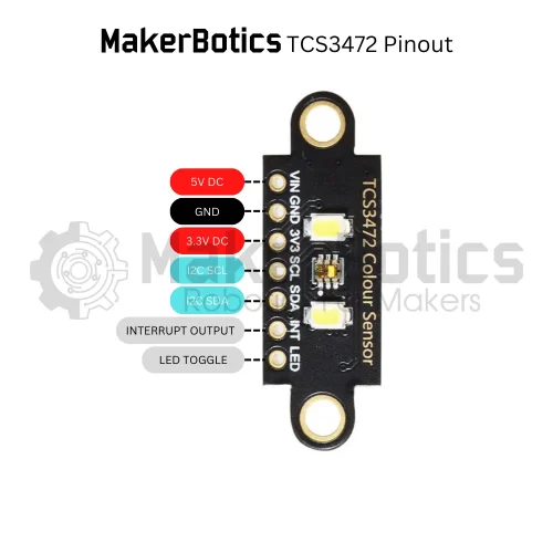
Pin Layout:
Below is a pinout table showing the connection mapping between the sensor and microcontroller.
| Sensor Pin | Teensy Pin |
| GND | GND |
| VCC | 3.3V |
| SDA | 18 |
| SCL | 19 |
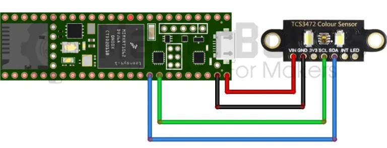
Setup:
- Connect the colour sensor’s SDA pin to pin 18 & SCL pin to pin 19 on the Teensy 4.1. Please refer to the wiring diagram above. To make wiring easier, you may use a breadboard with the male to male jumper wires.
- Open the Arduino IDE
- Plug in the Teensy 4.1 to the computer
Code Walk Through:
Libraries:
To access & use the colour sensor we include the Adafruit_TCS34725.h library by Adafruit. As the colour sensor uses I2C protocol to communicate with microcontrollers the Wire.h library is also needed. The Wire library is included in the Arduino IDE by default.
For information about the Adafruit_TCS34725 library: https://github.com/adafruit/Adafruit_TCS34725
Initiating the sensor:
Using the Adafruit_TCS34725.h library we can initialize the colour sensor and test if the connection is successful. If the sensor is found, it will print “Found Sensor” in the Serial Monitor. However if there is no sensor detection, “No TCS34725 found … check your connections” will be printed in the serial monitor
Measuring the RGB values:
The colour sensor takes 50ms to measure the RGB values, so we can set the delay to 60 ms when gathering the sensor readings, and then display the output.
Determining the predominant colour:
We can use a series of if-else comparison statements to determine which colour measurement is the highest and therefore the predominant colour.
We set the teensy to continuously gather & determine the colour measurements every 2 seconds.
Colour Detection Code:
The entire code for the tutorial is then put together and shown below.
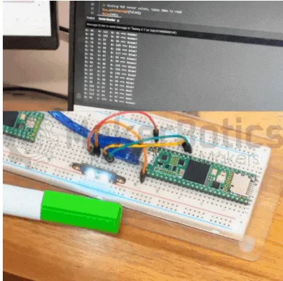
End Result:
After copying and pasting the above code into the Arduino IDE, upload it and it will automatically run. See below for the end results!
Place Red, Green and Blue coloured objects near the sensor and the output will be displayed in the serial monitor.
Pro Tip: Modify this code and add one of our displays to display the colour on a screen without the need for your computer!
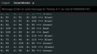
Serial Monitor Display
The correct colour type will be displayed here.
Further Ideas
Use this sensor and microcontroller to expand your project capability. Ideas include but are not limited to:
- Colour-coded pick and place robot
- Plant health monitor
- Colour-based sorting robot
Feel free to share your project with us; we’re excited to see your innovative applications!
Downloadable Content:
Please find this tutorial’s code on our GitHub page.
Credits:
- PJRC
- The Maker Community
- The STEM Community