
Search the Knowledge Base
Micro:Bit LED Switch Button Tutorial
Tutorial Aim:
To turn on an LED pin when the switch button is pressed and show a happy face on the microbit LED grid.
Requirements:
This tutorial makes use of the Micro:bit Electronics Learning Package
- Microsoft MakeCode for micro:bit
- Micro:bit V2
- Micro:bit Robot:bit Expansion Shield V2
- Breakout Board
- 5 FM Jumper Wires
- 1 Resistor
- 1 LED pin
- 1 Switch Button
Pin Layout:
| Micro:Bit Pins: | Switch Button Pins: |
| GND | GND |
| 1 | VCC |
| Micro:Bit Pins: | LED Pins: |
| GND | GND |
| 15 | VCC |
Setup:
Please refer to the diagram below for wiring. Please note that the circuit diagram uses a different Micro:bit shield than the supplied in our package, despite this, the wiring is the same.
- Place the LED pin on the breakout board using the transistor on the short leg, and connect to pin15 on the Micro:bit using the FM jumper wires on the longer leg
- Place the button switch on the breadboard and use the FM jumper wires to connect it to pin 1 on the Micro:bit
- Open Microsoft Makecode
- Plug in the Micro:bit to the computer

Code Walk Through:
Checking if the button was pressed:
We use conditional statements to determine whether the switch button is pressed. As the switch button may be pressed at any time, it’ll be continuously monitored.The code for this section will go inside the ‘forever’ block.
Creating a conditional block: Select the ‘if-else’ conditional block in the Logic tab
Checking if the button was pressed: Select “pin (pin number) is pressed” in the Input tab, change the pin number to 1 and place it in the empty conditional if slot.

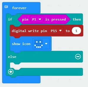
Turning on the LED & displaying a happy face on the LED grid:
To turn on the LED we send a signal to its corresponding pin.The code for this section will go inside the ‘if’ section of the conditional block.
- Turning on the led light if the button was pressed: Place the “digital write pin (pin number) to (value)” block (found in the Pins tab which is in the Advanced section) under the “if” statement, inside the conditional block and change the pin number to P15 and the value to 1
- Displaying a happy face on the LED grid when the button is pressed: Select “show icon” in the Basic tab, changing the icon to “happy” and placing it underneath the “if” statement
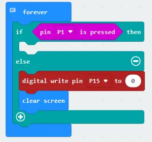
Turning off the LED & clearing the LED grid:
To ensure that the LED is off the LED grid is clear when the switch button is not pressed we’ll need to send an off signal to the LED’s pin & update the LED grid. The code for this section will go inside the ‘else’ section of the conditional block.
- Turning off the LED light when the button is not pressed: Select “digital write pin (pin number) to (value)”, place it underneath the else statement in the conditional block, and change the values to pin 15 and 0,
- Clearing the LED grid when the button is not pressed: Select “clear screen” in the Basic tab & place it underneath the else statement in the conditional block
Flashing the code onto the Micro:Bit:
- Make sure the Micro:Bit is connected to the computer
- On the bottom left corner, click the “Download” button and follow the prompts.
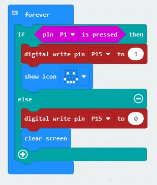
Block Code:
Entire block code for this tutorial
Python Code:
Entire python code for this tutorial.
Simulated Micro:Bit LED Grid:
Displaying the happy face on the grid when pin 1 receives input from the switch button
Simulated Button Switch & LED:
Displaying a happy face on the LED grid & activating the LED when the switch button is pressed.
Downloadable Content:
Please find this tutorial’s python & hex file for microsoft makecode on our Github.
Credits:
- Microsoft
- The Micro:bit Community
- The STEM Community